
Installation Manual

DispenseMate
®
553 Dispensing System
DispenseMate
®
555 Dispensing System
Quick Start Installation Guide
Dispensing Valve Configuration
Valve Model
Valve Air
Connection
Fluid Pressure
Connection
DJ-9000/DJ-2100 DispenseJet® Series P1 P2
DV-7000/DV-8000 Heli-Flow® Pumps* N/A P2
DV-01 N/A P2
DV-07 P1 P2
DV-03HPA P1 P2
DV-05A P1 P2
DV-07 P1 P2
DV-09 P1 P2
*When using the DV-7000 or DV-8000 valve, make sure the Valve Selector (U27) switch, located on the main board inside the electronics pan,
is set to the proper position. The default setting is DV-8000. The U27 switch setting does not affect any of the other valves. Refer to the
DispenseMate 550 Series User Guide for additional information.
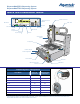
Main Power Circuit
Breaker
Main Power
Inlet
Discrete I/O
General
Purpose Inputs
General
Pur
p
ose Out
p
uts
RS-232 Port
Interlock
Main Air Inlet
Pressure Regulators
Z-head Connections
Cable Track
Start Button
EMO Button
ESD Grounding Strap
Connector
Vacuum Control
Pressure Gauges
Tooling Plate
Vision System
(Option)