
Manual


Introduction 5
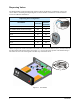
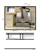
Front View Features
The figures in this section show views and features of the dispensing system. Callouts locate major
components, options, and switches seen in each illustration. Detailed operating instructions for some of
these features are treated in other sections of this manual. Front view features are shown in Figure 1-2.
1. Z-Head Dispenser Connections
All dispensing valves and dispensing options mounted to the Z-Axis are connected through this area.
2. Cable Track
The Cable Track houses electrical cables and pneumatic tubing to the Z-head.
3. Start Button
The Start button puts the dispensing system in a power-on state.
4. Emergency Machine Off
The EMO button is a built-in safety feature located on the front panel of the dispensing system.
Refer to the Safety section for additional information.
5. ESD Grounding Strap Connector
Grounding straps worn by the operator or technician plug into this jack to prevent electrostatic
discharge (ESD) damage to workpieces and dispensing system electronics during dispensing
operations and servicing.
6. Vacuum Control
The vacuum control allows low viscosity fluids, even water, to be consistently dispensed without
dripping between cycles. The vacuum exerts a negative pressure on the fluid pressure pneumatics
line when the valve is turned off.
7. Fluid Pressure Regulator
The Fluid Pressure Regulator and Gauge set supplies air to the fluid syringe.
8. Valve Pressure Regulator
The Valve Air Regulator and Gauge set supplies air pressure to the Dispensing Valve.
9. Computer System
The Computer System consists of a PC, a Color LCD Flat-Panel Monitor, ASCII Keyboard and
Mouse, and an Ethernet network port.