
Manual


50 Appendix A – Block Diagrams
Appendix A Block Diagrams
This appendix describes available pneumatic and electrical block diagrams and dispensing system
electronics that may help in understanding dispensing system operation and aid in troubleshooting. The
diagrams referred to in this appendix are listed in Table A-1 and are shipped with the dispensing system
manuals and accessories.
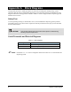
Safety First
Use of engineering drawings to disassemble, service, and reassemble the dispensing system promotes
good safety practices only when used in conjunction with the precautions in the Safety section and other
sections of this manual.
CAUTION! Only Asymtek-trained service technicians should perform troubleshooting,
servicing, and parts replacement.
List of Pneumatic and Electrical Diagrams
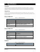
Table A-1 Block Diagrams
Drawing Number Title
7201232 Pneumatic Diagram, DispenseMate 550 Series
7201200BD Electrical Diagram, DispenseMate 550 Series
" NOTE Laminated 11" x 17" versions of diagrams referenced in Table A-1 are included with the
dispensing system.