
Manual

Operation 35
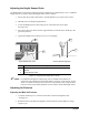
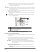
3. Rotate the knob clockwise until the Main Air Gauge registers 85 to 90 psi (586 to 620 kPa).
! If the Main Air Gauge fails to register pressure, verify that the dispensing system is
connected to the facility air source.
" NOTE The regulator assembly is equipped with a relief valve to protect the system components.
Increasing the pressure above 95 psi (655 kPa) may trigger the relief valve. If so, reduce
the air pressure below 95 psi.
4. Monitor the Main Air Gauge to make sure that pressure builds at a steady rate. Watch for
dropping pressure indicating an air leak.
! If there is an air leak, identify the source, shut off the facility air, and fix the leak before
proceeding.
TIP For accurate pressure adjustment, lower the pressure below the desired level and then
increase to the desired pressure.
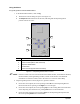
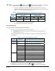
Item Description
1 Main Air Pressure Regulator
2 Main Air Pressure Regulator Inlet
3 Main Air Pressure Gauge
Figure 4-7 Main Air Pressure Regulator and Gauge
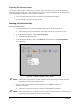
Adjusting the Valve and Fluid Pressure
1. Locate the Fluid and Valve Pressure Regulator adjustment knobs on the front Control Panel
(See Figure 1-2).
2. Rotate the regulator adjustment knob counterclockwise until the gauge registers 0 psi.
3. Rotate the appropriate knob clockwise until the Valve Pressure Gauge (P1) registers the air
pressure value (psi or kPa) required by your dispensing application.
" NOTE Valve and Fluid pressure settings depend on the fluid being dispensed and
Dispensing Valve being used. Refer to the manual applicable to the Dispensing
Valve on your system
4. Monitor the Pressure Gauge to make sure that pressure builds at a steady rate. Watch for
dropping pressure indicating an air leak.
! If there is an air leak, identify the source, shut off the facility air, and fix the leak before
proceeding.
1
2
3