
Manual

24 Installation
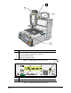
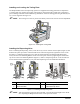
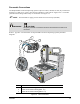
Installing and Leveling the Tooling Plate
The DispenseMate Series 550 Dispensing Systems are supplied with tooling plates that are adjusted to
± 127mm of the X-Y dispense level plane. The tooling is removed from the system prior to shipping to
prevent damage and must be reattached during installation. Attach the tooling plate using the four (4) m4
x 0.7 screws supplied. See Figure 3-2.
" NOTE The leveling set screws are preset at the factory and in most cases do not need adjustment.
Figure 3-2 Installing the Tooling Plate
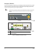
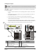
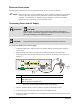
Installing the Dispensing Valve
Prior to installing the Dispensing Valve, loosen the six (6) screws on the Z-axis face plate (Figure A) and
slide the face plate up so that it is flush with the Z-axis extrusion (Figure B). Tighten the screws on the
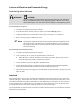
face plate. To install the Dispensing Valve, slide the dovetail bracket (included with the Dispensing
Valve) into the Valve Mounting Bracket on the Z-axis face plate. Secure by tightening the socket head
cap screw on the Valve Mounting Bracket (Figure C). Refer to “Dispensing Valves” in the Introduction
section and the manual applicable to your particular Dispensing Valve for additional information.
Item Description Item Description
1 Z-Axis Face Plate 3 Valve Mounting Bracket
2 Z-Axis Extrusion 4 Socket Head Cap Screw
Figure 3-3 Installing the Dispensing Valve
" NOTE After the Dispensing Valve has been installed, you must adjust the Height Sensor Probe.
See “Adjusting the Height Sensor Probe” in the Operation section.
3
1
4
2
Figure A Figure B Figure C