® DispenseMate 550 Series Dispensing System User Guide P/N 7201827, Revision B
NOTICE This is an Asymtek publication, which is protected by copyright. Original copyright date 2004. No part of this document may be photocopied, reproduced, or translated to another language without the prior written consent of Asymtek. The information contained in this publication is subject to change without notice. Manuals on the Internet For the convenience of Asymtek customers and field service representatives, copies of this manual can be downloaded from: http://www.asymtek.com/support/manuals.
Table of Contents 1 Introduction ......................................................................................................................................... 1 Overview ............................................................................................................................................... 1 Safety First ............................................................................................................................................ 2 Getting Started ...........
Operation ........................................................................................................................................... 27 Overview ............................................................................................................................................. 27 Theory of Operation ............................................................................................................................ 27 Basic System Operation ...............................
1 Introduction Congratulations on your choice of the DispenseMate® 550 Series Dispensing System! This manual is intended primarily as a reference for production operators. However, process engineers and service technicians unfamiliar with Asymtek products may also find this manual useful as a general introduction to the system.
Safety First Operation of your DispenseMate 550 Series Dispensing System involves air pressure, electrical power, mechanical devices, and the use of hazardous materials. It is essential that every person servicing or operating the dispensing system fully understands all hazards, risks, and safety precautions. Refer to the Safety section for additional information. WARNING! CAUTION! Consult the Material Safety Data Sheet (MSDS) for all fluids used with the dispensing system.
Standard Equipment Computer System The Computer system consists of the Computer, Monitor, Keyboard and Mouse. It runs Fluidmove for Windows NT (FmNT) software. Fluidmove for Windows NT Software Fluidmove for Windows NT (FmNT) is Asymtek proprietary software for use in a Windows NT environment, developed specifically for dispensing applications. Tooling Plate The Tooling Plate is mounted to the Y-axis and secures the workpiece for batch system operations.
Dispensing Valves The DispenseMate 550 Series Dispensing Systems support the following Asymtek jets, pumps, and valves. Refer to “Installing the Dispensing Valve” and “Pneumatic Connections” in the Installation section for additional information.
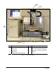
Front View Features The figures in this section show views and features of the dispensing system. Callouts locate major components, options, and switches seen in each illustration. Detailed operating instructions for some of these features are treated in other sections of this manual. Front view features are shown in Figure 1-2. 1. Z-Head Dispenser Connections All dispensing valves and dispensing options mounted to the Z-Axis are connected through this area. 2.
1 2 9 3 4 Item Description 5 6 7 8 Item Description 1 Z-Dispenser Connections 6 Vacuum Control 2 Cable Track 7 Fluid Pressure Gauge and Regulator 3 Start Button 8 Valve Pressure Gauge and Regulator 4 EMO Button 9 Computer 5 ESD Grounding Strap Connector Figure 1-2 Front View Features 6 Introduction
Dispensing Area The Dispensing Head, Valve, Camera, Height Sensor and Tooling Plate are located in the Dispensing Area (Figure 1-3). 1. Camera and Lens The compact, high resolution, black and white Camera and its vibration resistant lens are part of the Vision System. They are mounted on the Dispensing Head and are used to view work surfaces. 2. Dispensing Valve The Dispensing Valve controls or regulates the flow of material from a pressurized reservoir, such as a syringe.
Rear View Features Rear view features are shown in Figure 1-4. Callouts locate major components, options, and switches seen in each illustration. Detailed operating instructions for some of these features are treated in other sections of this manual. 1. RS232 Port The RS232 port connects the DispenseMate to the system Computer. 2. Discrete I/O There are four digital I/O’S, one analog I/O, and two 24-VDC solenoid drivers.
1 8 2 3 Item 5 4 Description Item 6 7 Description 1 RS232 Port 5 Interlock 2 Discrete I/O 6 Main Air Inlet 3 General Purpose Output Connector 7 Main Power Inlet 4 General Purpose Input Connector 8 Main Power Circuit Breaker Figure 1-4 Rear View Features Introduction 9
2 Safety Overview This section is intended to provide basic safety information necessary for operating and servicing the DispenseMate 550 Series Dispensing System.
Injury to Personnel If an injury occurs during operation or servicing of the dispensing system, it is recommended that the following steps be taken: 1. If the dispensing system is operating when the injury occurs, press the nearest EMO button to stop all system operations. 2. Immediately report injury to supervisor in accordance with facility procedures. 3.
• Do not touch the Dispensing Head and other moving parts while the dispensing system is operating. • To prevent burn injury, wear thermal gloves when working around Heater Tooling and Fluid Heaters. • Follow Material Safety Data Sheet (MSDS) recommendations for the proper handling, cleanup, and disposal of hazardous materials. • Always wear appropriate personal protective equipment (PPE) as recommended by facility safety practices and the material manufacturer’s MSDS.
Facility Environmental Health and Safety Practices Operators and technicians should know the closest location of the following safety related items in your facility: - Emergency Exits - Emergency Telephone - Eye-Wash Station - Fire Extinguisher - First Aid Station - MSDS Station 14 • If in a confined room, ensure adequate and uninterrupted air ventilation, heating, and cooling to meet environmental stress limits of personnel and the dispensing system.
Electrostatic Discharge (ESD) Precautions CAUTION! Personnel operating, maintaining, or servicing the dispensing system must follow ESD precautions. Failure to do so could cause severe damage to dispensing system electronic components and/or workpieces. Electrostatic Discharge (ESD), also known as “static discharge”, is the sudden transfer of electricity from one object or person to another object or person.
Safety Warning Labels Safety warning labels affixed to the DispenseMate 550 Series Dispensing System point out potentially hazard areas and remind personnel to take necessary safety precautions. Table 2-1 describes safety labels that may be affixed to the dispensing system. Locations of these warning labels are shown in Figure 2-1 and Figure 2-2. WARNING! CAUTION! Comply with all safety warning labels or serious injury to personnel or damage to the dispensing system may occur.
2 1 3 4 Item Description 1 Middle Pinch Hazard Warning Label 2 Left Pinch Hazard Warning Label (not shown) 3 Right Pinch Warning Label 4 Pinch Hazard Warning Label Figure 2-1 Safety Warning Labels, Front View Item 1 1 Description Electrical (Shock Hazard) Warning Label Figure 2-2 Safety Warning Labels, Rear View Safety 17
Emergency Shutdown In the event of an emergency or malfunction, press the Emergency Machine Off (EMO) button. The EMO is the large red button located on the front panel of the dispensing system. See Figure 2-3. Activating the EMO vents all pressure in the pneumatic system, de-energizes the servo power supply capacitors, and cuts power to all components except the Computer and Monitor.
Emergency Shutdown Situations As a minimum, activate the EMO in the following situations: WARNING! In an emergency, failure to completely shut down power to the dispensing system with the EMO can cause serious injury to the user and/or damage to the dispensing system. • If anyone is in immediate danger of being injured by moving parts, hazardous materials, or electrical shock. • If valuable dispensing system components or the workpieces are in danger of being damaged.
Lockout of Electrical and Pneumatic Energy Lock Out/Tag Out of AC Power WARNING! CAUTION! Lock out and tag out electrical power and pneumatic pressure when performing service or maintenance work on the dispensing system. Failure to do so could cause serious injury to the user and/or serious damage to the dispensing system. To lock out/tag out AC power: 1. Verify that all dispensing motion has stopped 2. Turn the Main Power Switch on the rear of the system to the OFF (0) position. 3.
3 Installation Overview This section describes installation procedures for the DispenseMate 550 Series Dispensing System and covers the following topics: • Facility Requirements • Pneumatic Connections • Uncrating and Placing the Dispensing System • Electrical Connections • Component Installation • Connecting Power and Air Supply Safety First Before performing any of the system installation procedures in this section, please review the information presented in the Safety section.
Uncrating and Placing the Dispensing System Tools and Materials Needed: • • Band Cutter Appropriate Personal Protective Equipment • • Hammer Flat Bar To uncrate and place the dispensing system: 1. Locate and remove the envelope on the outside of the shipping crate. Open the envelope and locate the shipping list. 2. Cut the four bands that secure the lid to the crate. Remove the lid, four cardboard corners, and plastic sleeve. 3.
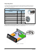
Installing the Computer CAUTION! " NOTE Make sure all power sources are disconnected before performing this procedure. All materials are included in the accessories crate that accompanied your DispenseMate. To install the Computer: 1. Locate the Computer and Monitor, remove all packaging material, and place it in the desired location. 2. Connect the RS-232 cable (P/N 7200897) to the rear of the DispenseMate and to COM 1 on the Computer. See Figure 3-1. 3.
Installing and Leveling the Tooling Plate The DispenseMate Series 550 Dispensing Systems are supplied with tooling plates that are adjusted to ± 127mm of the X-Y dispense level plane. The tooling is removed from the system prior to shipping to prevent damage and must be reattached during installation. Attach the tooling plate using the four (4) m4 x 0.7 screws supplied. See Figure 3-2. " NOTE The leveling set screws are preset at the factory and in most cases do not need adjustment.
Pneumatic Connections The DispenseMate 550 Series Dispensing System requires 85 l/min (1 SCFM) of clean, dry air delivered through a 12.7 mm (0.5 in.) pipe or hose at 90 psi (620 kPa). Connect the air supply to the ¼ -inch NPT quick-disconnect fitting at the Facility Air Connection. See Figure 3-5. " NOTE The maximum air supply pressure should not exceed 100 psi (689 kPa). WARNING! CAUTION! All system pneumatic connections should be checked before the main air is connected.
Electrical Connections The dispensing system requires 1 kw of single-phase power at 100, 120, 220, or 240 VAC. " NOTE Board wiring connections are installed in the factory before the product is shipped. Refer to the Specifications section for more information on electrical requirements. Refer to Appendix A for information on available electrical diagrams. Contact your Asymtek representative for requirements on your particular system.
4 Operation Overview Before operating your DispenseMate 550 Series Dispensing System, it may be helpful to familiarize yourself with the basics of how the system works.
Startup System Startup If necessary, refer to the figures in the Introduction section to identify system components. To power on the dispensing system: 1. Verify that the main power cord is connected to the Main Power Inlet and the facility power source. 2. Verify that the facility air is at the recommended pressure level and connected to the Main Air Pressure Regulator Inlet. See Figure 4-7. 3. Turn the Main Power Switch on the back of the system to the ON (I) position. 4.
4. When the FMNT Message 30416 - Dispenser Motor References Not Found appears, click OK to Home the Dispenser (Figure 4-1). Figure 4-1 FmNT Message 30416 ! The FmNT Main Window will open. See Figure 4-2. Figure 4-2 FmNT Main Window 5. Check to make sure the Dispensing Head is in the proper Home position. " NOTE If you receive any error messages, refer to the Troubleshooting section or to the FmNT User Guide or Online Help.
Using the Mouse To operate position controls with the Mouse: 1. In the FmNT Main Window, click on Jog. ! The Position Controls dialog box opens. See Figure 4-3. ! The Dispenser radio button will be selected, indicating that the Dispensing Head position controls are active.
" NOTE The single arrows and double arrows move the Dispensing Head or Tooling Plate different distances and different velocities per Mouse click. See Table 4-1. ! Clicking on Home sends the Dispensing Head to its home position. The home position is the extreme left front corner of the dispensing area, where the Dispensing Head X, Y, Z-axis coordinates are set to (0, 0, 0).
Safe Z-Height Safe Z-Height is determined by choosing a height that ensures the Needle, Height Sensor, Camera, Lighting, or any part of the Dispensing Head does not collide with any obstacles while traveling around the dispensing area. On the DispenseMate Series Dispensing Systems, the Camera is mounted to the Dispensing Head so that the Camera moves up and down with the Dispensing Valve.
Setting Safe Z-Height Safe Z-Height is the height below which the tip of Dispensing Head cannot go when moving from one set of coordinates to another during operation. To set the Safe Z-Height: 1. In the FmNT Main Window, click on Run a Program. ! The Production Window opens. 2. In the Production Window, click on the Setup button and then click on Setup Scripts. 3. Click on Teach Safe Z Height. ! The Teach Safe Z Height Window shown in Figure 4-5 opens. Figure 4-5 Teaching Safe Z Height 4.
Adjusting the Height Sensor Probe The Height Sensor Probe must be adjusted each time a different type of Dispensing Valve or a different length of needle is installed. Adjust the Height Sensor Probe as follows: 1. Power down the system as described in “System Shutdown” previously in this section. 2. Manually move the Dispensing Head down. 3. Loosen the Height Sensor Probe locking screw at the back of the Z-axis plate. See Figure 4-6. 4.
3. Rotate the knob clockwise until the Main Air Gauge registers 85 to 90 psi (586 to 620 kPa). If the Main Air Gauge fails to register pressure, verify that the dispensing system is connected to the facility air source. ! " NOTE The regulator assembly is equipped with a relief valve to protect the system components. Increasing the pressure above 95 psi (655 kPa) may trigger the relief valve. If so, reduce the air pressure below 95 psi. 4.
Adjusting the Vacuum Control The vacuum control (Figure 1-2) allows low viscosity fluids, even water, to be consistently dispensed without dripping between cycles. The vacuum exerts a negative pressure (suckback) on the fluid, thereby decreasing dripping. Adjust the Vacuum Control as follows: • Turn counterclockwise to increase vacuum pressure and decrease dripping. • Turn clockwise to decrease vacuum pressure. Starting a Production Run To start a production run: 1.
5. In the Production Window, click on the Load button. ! The Open dialog box will appear. 6. In the Open dialog box, select the program you wish to run and click on Open. See Figure 4-9. ! The current program name will appear in the Production Window. Figure 4-9 Production Window – Load Program 7. In the Production Window, click on Run and then click on the Run Production button. ! The Run Window opens. 8. Click on Go to start the dispensing process. See Figure 4-10.
System Shutdown Routine shutdown may vary depending on your particular requirements. However, it is recommended that you incorporate the following procedures into your production shutdown routine: Production Shutdown To shut down at the end of a production shift: 1. Wait for the dispensing program to complete and verify that all motion has stopped. 2. Unload all workpieces. 3. Remove the Dispensing Valve and clean as instructed in the appropriate valve manual. 4. Exit FmNT. 5.
5 Maintenance Overview Following a routine maintenance schedule and procedures can prevent part degradation and ensure high quality performance for every production run. Table 5-1 lists recommended maintenance procedures and intervals that will help to ensure quality dispensing and optimize system performance. Basic procedures are described later in this section.
Draining the Water Trap Because the facility air supply may contain moisture that can damage the dispensing system, the DispenseMate is equipped with a water trap that condenses this moisture before it enters the pneumatic system. The operator or technician must drain the water trap weekly or whenever it is full. Tools and Materials Needed: • • Box wrench Container for waste water To drain the Water Trap: 1. Locate the water trap at the rear of the system. 2.
Removing the Axis Covers In order to perform the remainder of the maintenance procedures described in this section, it will be necessary to remove the axis covers. See Figure 5-2. 1. Perform a “Service Shutdown” as described in the Operation section. 2. To remove the X-axis cover, loosen the two set screws and slide to the side. 3. To remove the Y-axis cover, remove the two screws at the back and pull it forward.
1 3 2 Item 4 Description 1 Tooling Plate 2 Y-Axis Cables 3 Z-Axis Cables (inside) 4 X-Axis Cables (inside) Figure 5-3 Mechanical Drive Cables Lubricating the XYZ-Axis Linear Guides " NOTE To perform the following procedure, you will need Asymtek Grease Kit P/N 7203262. The kit contains a grease syringe. 1. Remove the X- and Y-axis covers as described previously in this section. 2. Load the grease cartridge into the grease syringe. 3.
8. Put the tip of the grease syringe against the access hole and pump the grease syringe once or twice to inject an ample amount of grease into the housing. ! The housing is full when grease comes out of the ends. 9. Spread the excess grease along the length of the X-Axis linear guides. 10. Repeat Steps 5 to 7 for the Y and Z-axis linear guides.
4. Tension the Z-axis cables as follows: a. Remove the Tooling Plate. b. Manually push the Dispensing Head down. c. Loosen the two Z-axis tensioner block screws (Figure 5-5). d. Manually move the Dispensing Head up and down the full length of the axis. Repeat three to five times. e. Tighten the tensioner block screws. 5. When finished, replace the axis covers, tighten the screws and reattach the Tooling Plate.
6 Troubleshooting Overview If you have difficulty operating your dispensing system, use this section to identify a possible solution to the problem. If you have difficulties not listed in this section, or the suggested solution does not correct the problem, contact Asymtek Technical Support.
Basic System Troubleshooting System Power Table 6-1 System Power Troubleshooting Symptom No Power To Major System Components Possible Cause Recovery Procedures 1. The Start button has not been pressed. Press Start (l) on the Control Panel. 2. Main Power Cable is disconnected. Check that the Main Power Cable is connected to an AC source. 3. Main Power Circuit Breaker is OFF. Turn ON the Main Power Switch at the rear of the system. Turn the EMO button counterclockwise until it pops out. 4.
Dispensing Head Table 6-3 Dispensing Head Troubleshooting Symptom Possible Cause 1. No system power. No XYZ-Axis Dispensing Head Motion Recovery See System Power recovery procedures (Table 6-1). 2. Servo amps failed 3. +48V power supply down Contact a service technician. 4. Limits not cleared Dispense Head Fails to Find Home Dispense Head Starts To Move, Stops And Goes Open Loop Jerky Movement Dispenses at Wrong Zaxis Position 5. Home/Limit cable disconnected Connect Cable. 1.
Vision System Table 6-5 Vision System Troubleshooting Symptom No Image (FmNT display window is a solid pink color.) No Image (FmNT display window is dark or black.) Possible Cause 1. Camera is not connected. 1. Camera cable damaged. 1. Lighting intensity is too low. 2. Lighting module is disconnected. 4. Lighting module is not functioning properly. Contact a service technician. 1. Substrate is not within height focus limits of the Camera. Jog Z-Axis into focus.
7 Specifications Overview DispenseMate 550 Series Dispensing System specifications are presented in Tables 7-1 through 7-3. These specifications are intended as a convenient reference for personnel planning system relocation, installation, or operation, and others that may have an interest in system performance characteristics. Safety First Familiarity with the performance specifications and facility requirements in this section can provide information leading to safe operation of the dispensing system.
Appendix A Block Diagrams This appendix describes available pneumatic and electrical block diagrams and dispensing system electronics that may help in understanding dispensing system operation and aid in troubleshooting. The diagrams referred to in this appendix are listed in Table A-1 and are shipped with the dispensing system manuals and accessories.
Appendix B Parts List Overview This appendix contains a list of spare parts (Table B-1) and exploded view drawings (Table B-2) that will aid in ordering replacements parts for the DispenseMate 550 Series Dispensing System. Safety First Before attempting to replace any parts, please review the precautions in the Safety section. CAUTION! Only Asymtek-trained service technicians should perform troubleshooting, servicing, and parts replacement.
Illustrated Parts List Table B-2 Illustrated Parts List Figure Number Figure B-1 Figure B-2 Figure B-3 Figure B-4 Title Parts List, Front Panel Parts List, Electronics Assembly Parts List, Electronics Assembly, Continued Height Sensor 1 2 2 3 4 5 Item Number Part Number Description 1 198202 GAUGE, DIGITAL PRESSURE 2 40-1206 REGULATOR, PRECISION, 1-90 3 198870 SWITCH, EMO ACTUATOR 4 198867 SWITCH, START, ROUND, FLUSH BUTTON 5 198871 SWITCH, EMO, CONTACT BLOCK Figure B-1 Parts List, Fr
3 or 4 2x 5 2 1 6 4x 7 8 Item Number 1 2 3 4 5 6 7 8 Part Number 199229 199006 7201202 7201203 198300 7200170 55-5320 199280 Description ASSEMBLY, ELECTRONICS PAN, 325 ASSEMBLY, 100 Z ASSEMBLY, DRIVE, X, D-553 ASSEMBLY, DRIVE, X, D-555 ASSEMBLY, SERVO AMP PWA, DM MAIN, PROGRAMMED HEX POST, D-SUB, 4-40x5/16 INTERLOCK CONNECTOR Figure B-2 Parts List, Electronics Assembly Appendix B - Parts List 53
1 or 2 3 Item Number Part Number 1 199002 ASSEMBLY, 325 Y 2 199003 ASSEMBLY, 525 Y 3 198300 ASSEMBLY, SERVO AMP Description Figure B-3 Parts List, Electronics Assembly (Continued) 54 Appendix B – Parts List
1 2 Item Number Part Number Description 1 7200696 HEIGHT SENSOR ASSEMBLY 2 7200695 PROBE, 1.
Asymtek Headquarters 2762 Loker Avenue West Carlsbad, CA 92010-6603 USA Tel: (760) 431-1919 1-800-ASYMTEK (1-800-279-6835) P/N 7201827, Revision B © 2005