
User Manual
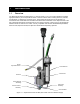
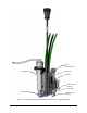
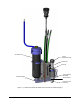

Table of Contents iii
Table of Figures
Figure 1-1 DispenseJet Series DJ-9500 (30cc Fluid Tube w/o Heat Exchanger) ...................................... 1
Figure 1-2 DispenseJet Series DJ-9520 (30cc Fluid Reservoir w/ Heat Exchanger) ................................. 2
Figure 1-3 DispenseJet Series DJ-9520 (6oz Fluid Tube w/ Heat Exchanger) .......................................... 3
Figure 3-1 DJ-9500 Exploded View ............................................................................................................ 8
Figure 4-1 Connection Diagram – Axiom X-1000 ..................................................................................... 11
Figure 4-2 Connection Diagram – Spectrum S-900 Series ...................................................................... 12
Figure 5-1 Connecting the Fluid Reservoir (30cc Fluid Tube w/o Heat Exchanger) ................................ 14
Figure 5-2 Connecting the Fluid Reservoir (30cc Fluid Reservoir w/ Heat Exchanger) ........................... 15
Figure 5-3 Connecting the Fluid Reservoir (6oz Fluid Reservoir w/ Heat Exchanger) ............................. 16
Figure 6-1 Disassembling Wetted Parts (DJ9520 w/Cup Seal and Unitized Nozzle shown) .................. 18
Figure 6-2 Removing the Seat .................................................................................................................. 19
Figure 6-3 Removing the Fluid Seal ......................................................................................................... 19
Figure 6-4 Cleaning the Static Seal .......................................................................................................... 20
Figure 6-5 Removing the Static Seal ........................................................................................................ 20
Figure 6-6 Nozzle, Seat, and O-ring Removal (Active Nozzle Pictured) .................................................. 21
Figure 6-7 Inserting the Cup Seal ............................................................................................................. 23
Figure 6-8 Seal Fully Inserted ................................................................................................................... 23
Figure 6-9 Assemble the Static Seal ......................................................................................................... 23
Figure 6-10 Place Static Seal on Needle .................................................................................................. 23
Figure 6-11 Seating the Static Seal .......................................................................................................... 23
Figure 6-12 Stroke Adjustment Assembly Fully Opened .......................................................................... 24
Figure 6-13 Inserting the Seat................................................................................................................... 24
Figure 6-14 Nozzle In Cavity Recess ........................................................................................................ 24
Figure 6-15 TCA Placed Over Nozzle ....................................................................................................... 24
Figure 6-16 Unitized Nozzle In Fluid Chamber Cavity Recess ................................................................. 25
Figure 6-17 Fluid Chamber/Unitized Nozzle Placed over Needle Assembly ............................................ 25
Figure 6-18 TCA Placed Over Unitized Nozzle......................................................................................... 25
Figure 6-19 Tightening the Collar ............................................................................................................. 25
Figure 6-20 Stroke Adjustment ................................................................................................................. 26
Figure 6-21 Unscrewing the Needle Assembly ......................................................................................... 27
Figure 6-22 Inserting the Needle Flange .................................................................................................. 27
Figure 6-23 Inserting the Needle .............................................................................................................. 28
Figure 6-24 Detaching the Needle from the Insertion Tool Base.............................................................. 28
Figure 6-25 Needle and Flange Fully Seated ........................................................................................... 28
Figure 6-26 Loosening the Four Socket Head Screws (DJ-9500) ............................................................ 30
Figure 6-27 Loosening the Four Socket Head Screws (DJ-9520) ............................................................ 31
Figure 6-28 Pushing the Coolant Line through the Junction Box ............................................................. 32
Figure 6-29 Removing the TCA Assembly ................................................................................................ 32
Figure 6-30 Attaching the TCA Assembly ................................................................................................. 32
Figure 6-31 Pulling the Coolant Line Back through the Junction Box ...................................................... 32
Figure 6-32 Pressing the TCA into the Junction Box ............................................................................... 33
Figure 6-33 TCA Electrical Connectors .................................................................................................... 33
Figure 6-34 Connecting the Solenoid ....................................................................................................... 33
Figure 6-35 Junction Box to Valve Body Alignment .................................................................................. 34
Figure 9-1 DJ-9500 Illustrated Parts List (Cup Seal, Standard Nozzle, and 30cc Mount) ...................... 51
Figure 9-2 DJ-9520 Illustrated Parts List (Cup Seal, Unitized Nozzle, and 30cc Mount) ........................ 52
Figure 9-3 DJ-9520 Illustrated Parts List (Static Seal, Active Nozzle, and 6oz Mount) ........................... 53