
User Manual


24 Maintenance and Service
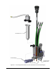
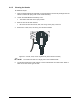
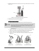
3. Adjust the stroke adjust knob so that the top of the red ring is visible at the top of the sleeve
(Figure 6-12).
Figure 6-12 Stroke Adjustment Assembly Fully Opened
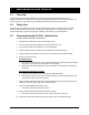
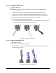
4. Insert the O-ring into the fluid chamber (Figure 6-13).
5. Install the seat and nozzle onto the fluid chamber.
Standard and Stinger Nozzles
a. Orient the seat with the lead-in angle toward the needle assembly (Figure 6-13).
CAUTION! Never use hard metallic tools on any mating or sealing surfaces. When properly
cleaned, aligned, and in good working condition, the seat will press into the
chamber with finger pressure only.
The seat should sit below the top surface of the cavity leaving a recessed area for
the nozzle to sit in.
b. Install the fluid chamber over the needle assembly and against the base of the jet body.
Make sure the chamber is engaged with the alignment pin in the jet body base.
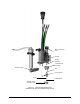
c. Place the nozzle into the recessed area above the seat Figure 6-14).
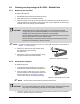
d. Install the TCA over the nozzle with the retainer fingers aligned in the open position
(Figure 6-15).
Figure 6-13
Inserting the Seat
Figure 6-14
Nozzle In Cavity Recess
Figure 6-15
TCA Placed Over Nozzle
Nozzle
TCA
O-ring
Seat
Sleeve