DispenseJet Series DJ-9500 Owner’s Manual
NOTICE This is a Nordson ASYMTEK publication, which is protected by copyright. Original copyright date 2008. No part of this document may be photocopied, reproduced, or translated to another language without the prior written consent of Nordson ASYMTEK. The information contained in this publication is subject to change without notice.
Table of Contents 1 2 3 Introduction ......................................................................................................................................... 1 1.1 Overview .................................................................................................................................. 1 1.2 Specifications ........................................................................................................................... 4 Safety .............................
7 8 6.7 Lubricating the Retainer Assembly and Stroke Adjustment Assembly .................................. 29 6.8 Removing and Replacing the Solenoid Valve or Thermal Control Assembly (TCA) ............. 30 Troubleshooting ................................................................................................................................ 35 7.1 Overview ................................................................................................................................ 35 7.
Table of Figures Figure 1-1 DispenseJet Series DJ-9500 (30cc Fluid Tube w/o Heat Exchanger) ...................................... 1 Figure 1-2 DispenseJet Series DJ-9520 (30cc Fluid Reservoir w/ Heat Exchanger) ................................. 2 Figure 1-3 DispenseJet Series DJ-9520 (6oz Fluid Tube w/ Heat Exchanger) .......................................... 3 Figure 3-1 DJ-9500 Exploded View ............................................................................................................
Table of Tables Table 6-1 Nozzle Cleaning Tools .............................................................................................................. 22 Table 7-1 DJ-9500 Troubleshooting – Symptom Based ........................................................................... 35 Table 7-2 DJ-9500 Troubleshooting – Set-up Based ............................................................................... 37 Table 7-3 DJ-9500 Troubleshooting – Component Based .....................................
1 Introduction 1.1 Overview The DispenseJet Series DJ-9500 (Figure 1-1 through Figure 1-3) is a non-contact dispenser providing high-speed delivery and exceptional volumetric control for various fluids, including silicones, underfill, encapsulants, UV adhesives, and silver epoxy. The DJ-9500 jets in tight spaces as small as 175 micrometers and creates fillet wet-out widths as small as 300 micrometers on the dispensed side of the die.
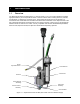
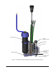
Stroke Adjustment Knob Fluid Reservoir Junction Box Solenoid Collar (Retainer Assembly) Fluid Chamber Heat Exchanger Thermal Control Assembly Figure 1-2 DispenseJet Series DJ-9520 (30cc Fluid Reservoir w/ Heat Exchanger) 2 Introduction
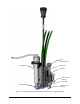
Fluid Reservoir Stroke Adjustment Knob Junction Box Solenoid Heat Exchanger Collar (Retainer Assembly) Fluid Chamber Thermal Control Assembly Figure 1-3 DispenseJet Series DJ-9520 (6oz Fluid Tube w/ Heat Exchanger) Introduction 3
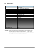
1.2 Specifications Characteristic Specification Size Width: 33 mm Height: 142 mm Depth: 100 mm (135mm w/ Body Heater) Seat and Nozzle Carbide / Stainless Steel Needle Assembly Carbide Fluid Seal PEEK or Flouroloy Fluid Chamber O-ring Ethylene Propylene or Viton Jet Body 6061-T6 Aluminum/Nickel Plated NPE 303 Stainless Steel Needle Assembly Bearings PEEK Thermal Control Body 6061-T6 Aluminum Nickel Plated Feed Tube Assembly Fitting Female Luer per ANSI/HIMA MD70.
2 Safety 2.1 Overview Dispensing system operation involves heat, air pressure, fluid pressure, mechanical and pneumatic devices, electrical power, and the use of hazardous materials. Refer to the safety section of your particular dispensing system Operations Manual prior to installing and operating your DispenseJet Series DJ-9500. Safety is considered a joint responsibility between the original equipment manufacturer (Nordson ASYMTEK) and the end-user (owner).
2.4 Preventing Equipment and Workpiece Damage • Immediately push the EMO button on the dispensing system if the dispensing system, DJ-9500, or a workpiece is in danger of being damaged. • Use standard Electrostatic Discharge (ESD) precautions when working near sensitive components. Always wear a grounding strap and connect it to the ESD ground before handling workpieces and equipment. • Perform all recommended DJ-9500 maintenance procedures at the suggested intervals.
3 Theory of Operation 3.1 Overview The DJ-9500 is a normally closed, air-actuated, spring-return mechanism, which uses momentum transfer principles to expel precise volumes of material. Pressurized air is regulated by a high-speed solenoid to retract the Needle Assembly from the seat. Fluid, fed into the fluid chamber, flows over the seat. When the air is exhausted, the needle travels rapidly to the closed position, displacing fluid through the seat and nozzle in the form of a droplet.
3.2.8 Body Heater The Body Heater helps hold the DJ-9500 at a constant temperature to protect it against transient temperature fluctuation in the machine. The Heat Exchanger version supplies fluid at a constant temperature.
4 Installation 4.1 Overview The DJ-9500 is designed for use on Nordson ASYMTEK DispenseMate, Axiom X 1000, Spectrum S-820, and Spectrum S-900 Series Dispensing Systems. This section includes installation instructions applicable for each of these systems. This section includes the following installation instructions: 4.
To install the DJ-9500: 1. Mount the DJ-9500 on the dovetail bracket and tighten with the 4-mm hex wrench. 2. Make the electrical connections according to the appropriate machine configuration shown in Figure 4-1 and Figure 4-2. 3. Connect the pneumatic hoses as shown in Figure 4-1 and Figure 4-2. You should hear a click when the hose is inserted properly. The black hose connects to valve air. The transparent green hose is used for nozzle cooling in elevated temperature environments.
Figure 4-1 Connection Diagram – Axiom X-1000 Installation 11
Figure 4-2 Connection Diagram – Spectrum S-900 Series NOTE 12 The connections in Figure 4-2 also apply to Nordson ASYMTEK’s DispenseMate and Spectrum S-820 platforms.
5 Setup 5.1 Overview This section describes the procedures required to setup the DJ-9500 for dispensing. 5.2 NOTE Refer to the Fluidmove User Guide for detailed instructions on software configuration. Safety First Dispensing system operation involves heat, air pressure, fluid pressure, mechanical and pneumatic devices, electrical power, and the use of hazardous materials.
Fluid Reservoir Fluid Chamber Feed Tube Assembly Figure 5-1 Connecting the Fluid Reservoir (30cc Fluid Tube w/o Heat Exchanger) 14 Setup
Fluid Reservoir Heat Exchanger Fluid Chamber Heat Exchanger Release Lever Figure 5-2 Connecting the Fluid Reservoir (30cc Fluid Reservoir w/ Heat Exchanger) Setup 15
Fluid Reservoir Heat Exchanger Heat Exchanger Release Lever Fluid Chamber Figure 5-3 Connecting the Fluid Reservoir (6oz Fluid Reservoir w/ Heat Exchanger) 16 Setup
6 Maintenance and Service 6.1 Overview Performing the recommended maintenance and service procedures increases the life of your DispenseJet Series DJ-9500 and ensures high quality dispensing performance for every production run. Refer to Figure 6-1 when performing the following maintenance and service procedures. 6.2 Safety First Dispensing system operation involves heat, air pressure, fluid pressure, mechanical and pneumatic devices, electrical power, and the use of hazardous materials.
Stroke Adjustment Knob Jet Body Needle Assembly Collar/Retainer Assembly Heat Exchanger Seal Fluid Chamber O-ring Unitized Nozzle Thermal Control Assembly (TCA) Figure 6-1 Disassembling Wetted Parts (DJ9520 w/Cup Seal and Unitized Nozzle shown) 18 Maintenance and Service
6.4 Cleaning and Inspecting the DJ-9500 – Wetted Parts 6.4.1 Removing the Cup Seal To remove the cup seal: 1. Disassemble the DJ-9500 as described previously. 2. Wipe fluid residue from the needle assembly. 3. Inspect the lower end of the jet body and inside the Thermal Control Assembly body and cooling passages for the presence of fluid. Wipe clear any fluid deposited on these areas and flush with 1.5 bar (22 psi) of pressurized air.
6.4.3 Cleaning the Static Seal To clean the static seal: NOTE The static seal does not need to be removed from the needle assembly for cleaning. 1. Gently wipe excess fluid from inside walls of the seal using a swab (P/N 7204301). 2. Turn the jet body so that the needle tip is pointing downward, place it over a container suitable to collect solvent, and flush the wetted seal surfaces thoroughly with the solvent. 3. Remove solvent from the seal using compressed air at 1.5 bar (22 psi). 4.
6.4.5 Cleaning the Nozzle To clean the nozzle: 1. Open the Stroke Adjustment Assembly (counterclockwise) until the red part aligns with the sleeve to release the spring load on the needle assembly. 2. Loosen the Collar/Retainer Assembly ½ turn. 3. Slide the TCA off the fluid chamber. 4. The retainer will rotate to the open position. Be careful to retain the nozzle, seat, and O-ring as they may come free.
Table 6-1 Nozzle Cleaning Tools Nozzle Sizes Part No. Nozzle Cleaning Tool 0.025mm (0.001in) 0.050mm (0.002in) Contact Nordson ASYMTEK customer service to order Nozzle Cleaner 0.075mm (0.003in) 7208918 VIAL WIRE,25PC., .0025 DIA 0.100mm (0.004in) 0.125mm (0.005in) 0.150mm (0.006in) 901935 KIT,WIRE,CLN,MUSIC W, .003” DIA. 0.200mm (0.008in) 0.250mm (0.010in) 901922 KIT,WIRE,CLN,MUSIC W, .007” DIA. 0.300mm (0.012in) 0.350mm (0.014in) 901923 KIT,WIRE,CLN,MUSIC W, .011” DIA. 0.400mm (0.
6.5 Assembling the DJ-9500 – Wetted Parts To assemble the wetted parts: 1. Ensure all wetted parts are clean and free of cured fluid. 2. Install the seal as described below: Cup Seal Insert the cup seal into the fluid chamber lip side first by placing the seal on the seal tool (P/N 7201416), and pushing the seal into the chamber (Figure 6-7 and Figure 6-8). Figure 6-7 Inserting the Cup Seal Figure 6-8 Seal Fully Inserted Static Seal a.
3. Adjust the stroke adjust knob so that the top of the red ring is visible at the top of the sleeve (Figure 6-12). Sleeve Figure 6-12 Stroke Adjustment Assembly Fully Opened 4. Insert the O-ring into the fluid chamber (Figure 6-13). 5. Install the seat and nozzle onto the fluid chamber. Standard and Stinger Nozzles a. Orient the seat with the lead-in angle toward the needle assembly (Figure 6-13). CAUTION! Never use hard metallic tools on any mating or sealing surfaces.
Unitized Nozzles a. Place the Unitized Nozzle into the recessed area of the Fluid Chamber (Figure 6-16). b. Install the Fluid Chamber/Unitized Nozzle over the needle assembly and against the base of the jet body. Make sure the chamber is engaged with the alignment pin in the jet body base (Figure 6-17). c. Install the TCA over the unitized nozzle with the retainer fingers aligned in the open position (Figure 6-18). Figure 6-16 Unitized Nozzle In Fluid Chamber Cavity Recess 6.
12. Reset the stroke to the proper value (according to applications requirements). Stroke Indicator Ring Cross Hole Mark Figure 6-20 Stroke Adjustment 13. Install the Fluid Reservoir onto the valve. DJ-9500 Version a. Install a clean feed tube assembly on the fluid chamber inlet. b. Install the Fluid Reservoir into the syringe holder and connect the feed tube assembly. See Figure 5-1. DJ-9520 Heat Exchanger Version a. Install the Fluid Reservoir onto the cleaned Heat Exchanger. b.
6.6 Removing and Replacing the Needle Assembly To remove the Needle Assembly: 1. Remove the DJ-9500 from the platform as described in 6.3 Disassembling the DJ-9500 – Wetted Parts previously in this section. 2. Wipe the fluid residue from the needle assembly. 3. Orient the jet with the needle assembly tip pointed upward. 4. Loosen the stroke adjustment assembly and remove it. 5. Use your fingers to push out the needle assembly.
4. Line up the needle with the inner seal and the jet bearings (Figure 6-23). 5. Slide the needle through the bearings and slide the insertion tool base into the jet body. 6. Hand-tighten the base until it stops against the jet body. Figure 6-23 Inserting the Needle 7. Line up the installation pin with the hole in the top of the base (Figure 6-24A). 8. Push the pin all the way into the base (Figure 6-24B). 9. Remove the pin (Figure 6-24C). 10.
12. Apply a light coating of lubricant (P/N 48-0018) to the inside of the sleeve on the detents and threads. WARNING! Failure to lubricate detents will lead to rapid wearing of the sleeve and failure. 6.7 13. Reinstall the Stroke Adjustment Assembly onto the jet body. 14. Reassemble the Fluid Chamber, Seat, Nozzle, and TCA. See 6.5 Assembling the DJ-9500 – Wetted Parts previously in this section. Lubricating the Retainer Assembly and Stroke Adjustment Assembly Perform quarterly, or as use dictates.
6.8 Removing and Replacing the Solenoid Valve or Thermal Control Assembly (TCA) To remove and replace the solenoid valve or TCA: 1. Remove the DJ-9500 from the platform and remove the fluid chamber, seat, and nozzle as described in 6.3 Disassembling the DJ-9500 – Wetted Parts previously in this section. 2. Wipe the fluid residue from the needle assembly. 3. Separate the Solenoid from the Jet Body. DJ-9500 Version a.
DJ-9520 Heat Exchanger Version a. Pull down the Heat Exchanger Handle to release and remove the Heat Exchanger. b. While the Release Handle is still down, loosen the four socket head cap screws using a 2.5 mm hex wrench through the holes in the cover on the junction box (DO NOT remove the three (3) button head screws). c. Remove the solenoid, junction box, Heat Exchanger Handle, and Reservoir as a unit from the jet body.
4. Disconnect the 2-pin connector and remove the solenoid valve. 5. Replacing the TCA only: a. Disconnect the 4-pin connector. b. Push the translucent green coolant line into the junction box to gain access to the TCA connection (Figure 6-28). c. Apply a light coating of lubricant (P/N 48-0018) to the line to ease the movement. Disconnect the black portion of the TCA coolant line from the barbed coolant fitting and remove the TCA (Figure 6-29). Take care not to damage the coolant fitting.
f. Press the long, black portion of the TCA into the groove on the junction box (Figure 6-32). g. Attach the electrical connectors on the TCA (Figure 6-33). Figure 6-32 Pressing the TCA into the Junction Box 6. Figure 6-33 TCA Electrical Connectors Reconnect the 2-pin connector for the solenoid valve (Figure 6-34). Figure 6-34 Connecting the Solenoid 7. Reassemble the junction box, solenoid and jet body.
DJ-9500 Version a. Thread in the four (4) socket head cap screws. Make sure the two (2) O-rings are properly seated in the jet body. NOTE b. Tighten the four (4) socket head cap screws with a 2.5 mm hex wrench. DJ-9520 Heat Exchanger Version a. With the cam lever down to the open position, thread in the four (4) socket head cap screws. b. Attach the Valve Body Alignment Tool (P/N 7214835) to the Junction Box and Collar and tighten the adjustment knob hand tight.
7 Troubleshooting 7.1 Overview To quickly identify problems, look for obvious signs such as burnt, missing, damaged, or loose parts, as well as fluid obstructions and leakages. If a problem recurs, there may be other root causes. Table 7-1 through Table 7-3 facilitate troubleshooting based on symptom, set-up, and component. Refer to Figure 9-1 to Figure 9-3 for part identification. 7.
Table 7-1 DJ-9500 Troubleshooting – Symptom Based (Continued) Symptom Poor Quality Jetting Air Leak Leakage of Fluid through Weep Hole Possible Cause Any of the causes above As above. Changed software settings Check dot parameters and jet configuration values. Dirty, worn, or damaged wetted parts (fluid chamber, fluid seal, chamber O-ring, seat, nozzle, needle assembly) Thoroughly clean. Inspect all sealing and mating surfaces for scratches and traces of fluid.
Table 7-2 DJ-9500 Troubleshooting – Set-up Based Set-up Variable Effect Notes Dispense Volume and Quality If this is a new process, contact Nordson ASYMTEK for assistance in process development. If this is a qualified process, fluid properties may have changed. The fluid may have exceeded its pot life, or been mishandled or set-up incorrectly. In addition, air bubbles are a common problem in mixed, high viscosity fluids.
Table 7-3 DJ-9500 Troubleshooting – Component Based Component Quality Troubleshooting Questions Seat Size and orientation Is it the correct size? Was it installed in the correct orientation? Does a new seat have the same behavior? Nozzle Size and cleanliness Is it the correct size? Was it cleaned completely? Does a new nozzle have the same behavior? Stroke Adjustment Adjustment position Was the Stroke Adjustment Assembly removed? Was the stroke adjustment set following the procedure? Is the Needl
8 Additional Information 8.1 Recommended Facility Items In addition to the supplied accessories and tools, it is recommended that the following items be available at your facility: 8.
8.
8.4 Needle Assembly, Nozzle, and Seat Configuration The DispenseJet Series DJ-9500 is configured at the Nordson ASYMTEK factory for your application. Configuration includes selecting appropriate needle/nozzle and seat sizes and identifying the model of the machine on which the jet will be installed. The optimal needle, nozzle and seat combination is determined based on your application needs. Table 8-1 shows available options and part numbers. Contact Nordson ASYMTEK for additional information.
Table 8-1 Available Needle/Nozzle and Seat Sizes (Continued) Part No. Description For Standard Nozzles: 42 210734-1 SEAT, C TYPE, 0.20mm (0.008in) 210734-2 SEAT, C TYPE, 0.25mm (0.010in) 210734-3 SEAT, C TYPE, 0.38mm (0.015in) 210734-6 SEAT, C TYPE, 0.75mm (0.030in) 210734-8 SEAT, C TYPE, 1.00mm (0.040in) 210734-12 SEAT, C TYPE, 1.50mm (0.060in) 210753-3 NOZZLE, LOW VOL, DJ-9000, 0.075mm (0.003in) 210753-4 NOZZLE, LOW VOL, DJ-9000, 0.100mm (0.004in) 210753-5 NOZZLE, LOW VOL, DJ-9000, 0.
Table 8-1 Available Needle/Nozzle and Seat Sizes (Continued) Part No. Description For Active Nozzles: 7216389-1 SEAT, ACTIVE, Z TYPE, 0.125mm (0.005in) 7216389-2 SEAT, ACTIVE, Z TYPE, 0.15mm (0.006in) 7216389-3 SEAT, ACTIVE, Z TYPE, 0.20mm (0.008in) 7216389-4 SEAT, ACTIVE, Z TYPE, 0.25mm (0.010in) 7216389-5 SEAT, ACTIVE, Z TYPE, 0.38mm (0.015in) 7216389-6 SEAT, ACTIVE, Z TYPE, 0.75mm (0.030in) 7216389-7 SEAT, ACTIVE, Z TYPE, 1.50mm (0.059in) 7216390-1 SEAT, ACTIVE, C TYPE, 0.125mm (0.
8.5 Spares and Accessories Table 8-2 and Table 8-3 list available spares and accessories. You may order entire kits or by individual part number. Table 8-2 DJ-9500 Spares and Accessories Part Number 44 Part Description Description Valve Cleaning/ Consumables Kit 7200538 01-0022-00 193840 210765 48-0018 58-0036 58-0037 58-0038 7200578 7204301 7204302 7208918 901922 901923 901924 901935 955055 LABEL KIT, CONSUMABLE, VALVE, DJ-9500 BOOT,VAC .
Table 8-3 DJ-9520 Spares and Accessories Part Number Part Description Description 7214872 193840 210765 901922 901923 901924 901935 955055 7200578 7204301 7204302 7208918 01-0022-00 48-0018 58-0036 58-0037 58-0038 LABEL 7214868 KIT, CONSUMABLE, VALVE, DJ-9520 SWAB,RND/RND TIP,10/PKG ASSY,FEED TUBE,FLUID,PKG-50 KIT,WIRE,CLN,TUNG,.007"DIA KIT,WIRE,CLN,TUNG,.011"DIA KIT,WIRE,CLN,TUNG,.014"DIA KIT,WIRE,CLN,TUNG,.003"DIA SEAL,FLUOROLOY G,.313X.125 O-RING,.22"ID X .032"CS,70EP SWAB,1.
8.6 Sample Application Settings See Table 8-4 and Table 8-5 for a list of settings that affect DJ-9500 performance. Values are application dependent. Refer to the Fluidmove User Guide or Online Help for detailed software instructions. Values are saved in the Fluidmove configuration, fluid, heater, and program files. A column is provided for you to record your current settings.
Table 8-5 Software Settings (Continued) Category Teach a Program>Edit>Edit Dot Parameters Parameter Units Current Settings Settling Time sec Down Speed inch/sec Down Accel inch/sec Dispense Gap 2 inch Num Shots Multi-shot Delta Dwell inch Dwell Time sec Retract Distance inch Retract Speed inch/sec Retract Accel inch/sec Mid-move 1 inch Mid-move 2 inch 2 On Vector Mode Off Vector Mode Post Dwell sec Teach a Down Speed Program>Edit>Edit Line Down Accel Parameters Dispense Gap Spe
9 Illustrated Parts List Table 9-1 identifies components referred to in Figure 9-1 to Figure 9-3. The item numbers associated with the description correspond to the callout numbers in the illustration. Part number information is also available on Nordson ASYMTEK’s Find-A-Part web page: http://webstore.asymtek.com/awweblive/apps/findapart_index.asp Table 9-1 Illustrated Parts List Item No. Part No.
Table 9-1 Illustrated Parts List (Continued) Item No. Part No. 33 7214821 ASSY, J-BOX,DJ-9500,W CLAMP 34 7214840 ASSY, J-BOX,BODY HEATER,DJ-9500 35 7214890 ASSY, J-BOX, NO-HEAT, DJ9500 36 49-3330 SCREW,M3X.05, COSKET CAP X30 (Torque to 12in-lbs) 37 7212295 DRAW PLATE HEAT EX, DJ9500 48-9930 7212288 7212292 7212293 985432 7212305 195444 7212291 49-3208 CAM RELEASE MECHANISM PIN.DOWEL,.125 X .438 LG CAM,HEAT EX, DJ-9500 ADJ PLATE HEAT EX, DJ-9500 LINKAGE HEAT EX, DJ-9500 PIN,DOWEL,.125 X .
1 2 3 7 4 9 5 12 6 30 8 32 10 34 35 11 47 13 15 16 14 46 31 30 48 21 22 27 11 23 36 41 28 42 49 29 Figure 9-1 DJ-9500 Illustrated Parts List (Cup Seal, Standard Nozzle, and 30cc Mount) Illustrated Parts List 51
1 2 3 9 7 4 12 5 6 8 32 30 10 15 33 11 13 16 37 14 19 38 31 30 39 30 43 11 23 24 45 36 50 40 29 Figure 9-2 DJ-9520 Illustrated Parts List (Cup Seal, Unitized Nozzle, and 30cc Mount) 52 Illustrated Parts List
1 2 3 4 9 5 12 7 6 30 8 32 33 10 17 37 38 11 13 18 44 14 20 39 31 30 45 30 11 23 36 51 40 25 26 29 Figure 9-3 DJ-9520 Illustrated Parts List (Static Seal, Active Nozzle, and 6oz Mount) Illustrated Parts List 53
Nordson ASYMTEK Headquarters 2762 Loker Avenue West Carlsbad, CA 92010-6603 USA Tel: (760) 431-1919 P/N 7218010, Revision E © 2011