
Manual

Maintenance and Service 33
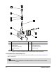
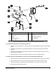
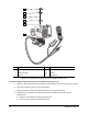
Item Description Item Description
1 U-cup Seal 6 U-cup Seal
2 Upper Body 7 O-ring
3 Fitting 8 Hex Head Screw (four)
4 Elbow Connector 9 Solenoid Valve
5 Lower Body 10 Plug
Figure 5-5 Reassembly of the Upper and Lower Bodies and Solenoid Valve
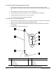
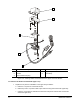
To insert the Seat Extension into the Heater (Figure 5-6):
1. Reapply the conductive grease on the seat extension without putting any grease on the threaded
shaft.
2. Position the seat extension so that the dowel pinhole on the seat extension faces toward the
backside.
3. Rotate the seat extension into the heater to spread the conductive grease evenly and to avoid
the formation of air pockets.
4. Thoroughly wipe off any excess conductive grease from the seat extension threads.
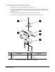
To attach the Heater and Seat Extension to the Lower and Upper Bodies (Figure 5-6):
1. Position the heater and seat extension to the lower and upper bodies as shown in the illustration.
2. Align the attachment holes for the heater, seat extension, and the upper and lower bodies.
3. Using a torque wrench, install the two screws and tighten to a torque of 0.79 N-m (7 in-lb).
4. Set aside the assembled components.
1
3
4
5
9
10
8
8
2
6
7