
Manual

22 Maintenance and Service
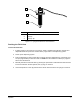
3. Lower the fluid pressure to zero (0) and disconnect the clear pneumatic line (fluid pressure) and
remove the syringe.
CAUTION! Follow Material Safety Data Sheet (MSDS) recommendations for the proper
handling and disposal of fluids.
4. Shut down the dispensing system.
Refer to the manual applicable to your dispensing system when performing steps 3 and 4.
If the micro-adjustment assembly is set to a specific setting, make a note of this setting for
future reference.
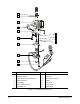
Disassembling the DispenseJet
Cleaning and inspection require disassembly of major components and small and intricate parts of the
DispenseJet. Refer to Figure 5-1, unless otherwise noted. This procedure assumes that the co-axial air
solenoid valve and nozzle are installed.
To disassemble the DispenseJet:
1. Using the provided torque wrench, remove the standard nozzle nut and co-axial air nozzle nut.
2. Remove the air tubing from the co-axial air nozzle nut.
3. Remove the co-axial air nozzle nut from the standard nozzle nut.
4. Loosen the micro-adjustment as follows:
a. Turn the micro-adjustment cap 4 to 6 turns counterclockwise.
b. Use the spanner wrench to loosen the lock nut.
c. Turn the preload screw to relieve compression on the compression spring.
5. Remove the seat extension and heater as follows:
a. Use the hex key to remove the two screws securing the heater and the seat extension to the
lower body.
b. Separate the seat extension from the heater.
c. Remove the exposed large o-ring.
d. Set aside the disassembled parts for cleaning.
CAUTION! Handle o-rings and seals carefully. If o-rings or seals are damaged, leakage
or premature DispenseJet failure may occur.
NOTE The seat extension has special thermally-conductive grease applied to the non-
threaded portion of the shaft. If the grease is accidentally removed, apply new
conductive grease.