
Manual

8 Installation
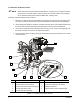
To Install the Air Assist Feature:
NOTE These instructions assume that the air assist feature, consisting of the co-axial air solenoid
valve and the co-axial air nozzle nut and air tubing, has not been installed. Once installed,
the co-axial air solenoid valve remains installed when not being used.
Install the co-axial air solenoid valve as follows:
1. Attach the co-axial air solenoid valve bracket to the bottom of the Z-head mounting plate using
two 2-mm hex screws with removable thread-locking adhesive ensuring a secure attachment.
2. Using a flathead screwdriver, install the co-axial air solenoid valve to the installed bracket using
the two screws with removable thread-locking adhesive ensuring a secure attachment.
3. Connect the co-axial air solenoid valve electrical connector to the
co-axial air jack (typically near
the heater controller connectors on the dispensing system).
4. Connect the blue (green or black) tubing from the dispensing system pneumatics to the co-axial
air solenoid valve.
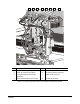
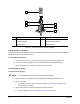
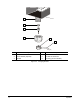
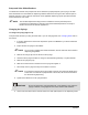
Item Description Item Description
1 Co-axial Air Pneumatic Valve Tubing 6 Bracket Mounting Screw (two)
2 Co-axial Air Electrical Connector 7 Co-axial Air Nozzle and Air Tubing
3 Co-axial Air Solenoid Valve Screw (two) 8 Standard Nozzle Nut
4 Co-axial Air Solenoid Valve 9 Z-head Mounting Plate (Valve Bracket)
5 Co-axial Air Solenoid Bracket
Figure 3-3 Installing the Air Assist Feature
4
5
6
3
9
8
7
2
1