
User guide

26 Maintenance and Service
Disassembly of the DispenseJet
Inspect each part during the disassembly for wear and tear or damage. For parts replacement, remove and
disassemble the DispenseJet to the level necessary to gain access to the failed part.
CAUTION! Do not subject the electrical cables to stress during removal. Damaged cables cannot
be replaced separately and can only be replaced with the next higher assembly.
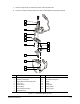
To remove the Solenoid Valve from the Upper Body (Figure 5-2):
1. If not already removed, remove the two hex-head screws securing the solenoid valve to the
upper body.
2. Remove the solenoid valve and set it aside.
To disassemble the Micro-Adjustment and associated parts (Figure 5-2):
1. Make a notation of the setting before disassembling the micro-adjustment.
CAUTION! To prevent damage to the needle and seat extension, loosen the micro-adjustment
by turning it counterclockwise. This reduces the needle pressure on the seat.
2. Turn the micro-adjustment 4 to 6 turns counterclockwise.
3. Inspect the micro-adjustment for damage, wear and tear, or play in the moving mechanism. If
damaged, loosen the setscrews, remove the micro-adjustment and obtain a replacement.
4. Using the spanner wrench, loosen the preload locking nut.
5. Carefully remove the preload screw from the cap and the micro-adjustment while:
a. Observing the compression spring in the viewing window of the preload screw.
b. Counting the number of turns it takes to release contact on the compression spring.
6. Remove the compression spring from the cap.
7. Set aside the disassembled parts for cleaning and inspection.