
User guide

12 Operation
Theory of Operation
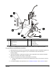
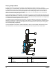
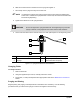
A typical cross-section of the internal workings of the DispenseJet is shown in Figure 4-1. During a
dispensing cycle, a solenoid-driven air pressure valve compresses a spring. The compressed spring retracts
a needle plunger and the fluid chamber space vacated by the needle plunger is filled with fluid. When air
exhausts from the solenoid valve, the spring expands and the needle plunger returns to its seat with an
impact force that ejects the fluid through the dispensing nozzle onto the substrate and then immediately
blocks the fluid from flowing through the nozzle.
Fluid to be dispensed by the DispenseJet is contained in a syringe (or an external reservoir) and is fed to the
DispenseJet fluid chamber at 7 to 69 kPa (1 to 10 psi). To stabilize viscosity and improve flow characteristics
of the fluid, the fluid is fed through a heater that typically warms the fluid from the ambient room temperature
to an ideal and controlled temperature of 40
o
C (104
o
In the jetting process, the DispenseJet moves in the X-Y plane to dispense a variety of pre-programmed
patterns in a confluence to create a uniform film of fluid. There is no movement required in the Z-axis during
or between the dispense cycles. The fluid dispensed on the substrate forms a dot or a jet-on-the-fly (JOF)
line of dots depending on application.
F).
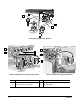
The micro-adjustment controls the needle travel distance. When turned clockwise, it decreases the piston
travel and fluid flow, and when turned counter-clockwise it increases the piston travel and fluid flow.
Item Description Item Description
1 Micro-Adjustment 4 Needle
2 Spring 5 Heater
3 Air Piston 6 Nozzle
Figure 4-1 Typical Jet DispenseJet Internal Workings
1
2
3
4
5
6