DispenseJet Series DJ-2100 Owner’s Manual P/N 199418
Notice This is a Nordson ASYMTEK publication, which is protected by copyright. Original copyright date 2002. No part of this document may be photocopied, reproduced, or translated to another language without the prior written consent of Nordson ASYMTEK. The information contained in this publication is subject to change without notice. Manuals on the Internet For the convenience of Nordson ASYMTEK customers and field service representatives, copies of Nordson ASYMTEK manuals can be downloaded from: www.
Table of Contents 1 Introduction ..........................................................................................................................................1 Overview ................................................................................................................................................1 Safety First .............................................................................................................................................1 Model Differences .........
Spare Parts ..........................................................................................................................................44 Nozzle Kits ...........................................................................................................................................46 Mounting Brackets ...............................................................................................................................46 Spare Part Kits .........................................
1 Introduction Overview This section provides you with an introductory description of the DJ-2100 Series DispenseJet. More details are provided in the sections that follow on how to properly install, operate, and maintain the DispenseJet. This section covers: • Model Differences • DispenseJet Description • Specifications Safety First Please refer to the Safety section of this manual and the Safety section of the applicable Dispensing System Manual before using the DJ-2100 Series DispenseJet.
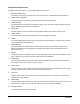
DispenseJet Components The major components (Figure 1-1) are briefly described in this section. 1. Black Pneumatic Hose The Black Pneumatic Hose connects to the Valve Connection on the Dispensing System Bulkhead. 2. Height Sensor (optional) The Height Sensor is an option for measuring and recording substrate height. 3. Solenoid Valve This Solenoid Valve compresses and expands a spring, which controls the needle that ejects the fluid through the dispensing nozzle onto the substrate. 4.
14. Preload Screw The Preload Screw regulates dispense quality by controlling spring tension during the dispensing needle stroke. 15. Micro-Adjustment The Micro-Adjustment controls the needle travel distance. When turned clockwise, it decreases needle travel and fluid flow. When turned counterclockwise, it increases the needle travel and fluid flow.
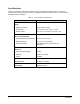
Specifications Table 1-2 contains the technical specifications for the DJ-2100 Series DispenseJet. If you have any questions about facility requirements, refer to applicable Dispensing System manual or contact Nordson ASYMTEK Technical Support. Table 1-2 DJ-2100 Series Specifications Element Parameters Valve: Weight (dry weight): 380 g (without syringe) Syringe Size: 5, 10, or 30 cc (0.17, 0.34, or 1.0 oz) Reservoir Size: 177 or 591 cc, 3.
2 Safety Overview This section describes the precautions to be taken to promote personal safety and safe use of the DJ-2100 Series DispenseJet. Dispensing system operation involves heat, air pressure, fluid pressure, mechanical and pneumatic devices, electrical power, and the use of hazardous materials. Refer to the Safety section of your particular dispensing system Operations Manual prior to installing and operating your DJ-2100 Series DispenseJet.
Preventing Equipment and Workpiece Damage • Immediately push the EMO button on the dispensing system if the dispensing system, DJ-2100, or a workpiece is in danger of being damaged. • Use standard Electrostatic Discharge (ESD) precautions when working near sensitive components. Always wear a grounding strap and connect it to the ESD ground before handling workpieces and equipment. • Perform all recommended DJ-2100 maintenance procedures at the suggested intervals.
3 Installation Overview The DJ-2100 is designed for use on Nordson ASYMTEK Century C-718/C-720, Millennium M-2000, and Axiom X-1000 Series Dispensing Systems. This section covers: • Unpacking the DispenseJet • Installation Instructions Safety First Before performing any of the installation procedures in this section, please review the information presented in the Safety section.
Installation Instructions If the DJ-2100 Series DispenseJet was factory installed, you can proceed directly to the Operation section after removing all packing material from the Jet. If not, proceed as follows: Installing the DispenseJet The instructions below are for the standard SMA application platform, the C-718 Dispensing System. Installations on other dispensing systems such as the M-2000 and X-1000 series may vary slightly.
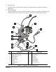
1 2 8 3 4 5 7 6 Item Description Item Description 1 Syringe Bracket 5 Set Screw Mounting Holes 2 Bracket Mount 6 RTD Cable 3 Pins 7 Heater Cable 4 Valve Bracket 8 Mounting Screws Figure 3-2 Installing the DJ-2100 Series DispenseJet - Century C-718 Dispensing System To make electrical and pneumatic connections: 1. Make the electrical connections according to the appropriate machine configuration (Figure 3-3). 2. Connect the pneumatic hoses (Figure 3-3).
2 1 4 3 Century Series Dispensing Systems 1 3 2 4 1 2 4 Millennium M-2000 Series Dispensing Systems Item Description Axiom X-1000 Series Dispensing Systems Item Description 1 Black Pneumatic Line (Valve) 3 Heater/Temperature Controller Connection 2 Clear Pneumatic Line (Fluid) 4 Solenoid Valve Figure 3-3 Typical Electrical Cable, Fluid, and Air Line Connections 10 Installation
4 Operation Overview This section covers the requirements and the necessary steps to properly operate the DJ-2100 Series DispenseJet. This section covers: • Theory of Operation • Operating Instructions • Application and Process Development Safety First Before you operate the DispenseJet, make sure you understand and follow the precautions in the Safety section. WARNING! Follow proper startup and shutdown procedures for the dispensing system when making adjustments or changing fluids.
Theory of Operation A typical cross-section of the internal workings of the DispenseJet is shown in Figure 4-1. During a dispensing cycle, a solenoid-driven air pressure valve compresses a spring. The compressed spring retracts a needle plunger and the fluid chamber space vacated by the needle plunger is filled with fluid.
Operating Instructions Prior to using the DispenseJet for production runs, it is recommended that you conduct a brief test-run to verify that adjustments and parameters are set for optimum performance. NOTE Read the entire section before operating the DispenseJet. The sequence of events may vary for your particular application. CAUTION! Operations should be performed by trained personnel only.
5 0 0 5 20 1 2 6 3 5 4 Item Description Item Description 1 Micro-Adjustment 4 Cap 2 Preload Locking Nut 5 DispenseJet Cap Markings 3 Preload Screw 6 Preload Window Figure 4-2 Preload and Micro-Adjustment Settings Setting the Micro-Adjustment To make adjustments that may be necessary to regulate fluid volume while the DispenseJet is installed on the dispensing system, proceed as follows: To set the Micro-Adjustment: 1.
Preparing the DispenseJet for Fluid Dispensing The following assumes that the correct nozzle has been selected and installed. See the Appendix for available nozzles for the DJ-2111, DJ-2112, and DJ-2114 DispenseJets. To prepare the DispenseJet for fluid dispensing: 1. Verify that the nozzle functions properly by activating the solenoid valve either manually using the solenoid valve push button or automatically from the dispensing system software.
6. Slide the receiver head onto the flat end of the syringe and tighten it. 7. Place the tip of the syringe securely into the luer-lock. NOTE 8. It is important to position the receiver head so that the long sides are parallel to the X-axis rods. If it is slanted or perpendicular to the X-axis, the receiver head will hit the Z-head during dispensing. Tighten the thumbscrew on the syringe bracket. CAUTION! 9. Do not over-tighten the syringe thumbscrew.
Purging the DispenseJet NOTE This procedure is not necessary if you have just performed a Prompted Setup routine or manually primed the DispenseJet. Tools and Materials Needed: • 0.050-inch hex key • Tissue wipes • Gloves WARNING! Refer to the Material Safety Data Sheet (MSDS) for handling, health, chemical, safety, and disposal information for all fluids and materials before use. All fluids and materials must be disposed of according to local regulations.
4. Using a cloth or tissue, clean the seat on the bottom of the extension. WARNING! 5. Wear gloves when cleaning underneath the extension to prevent the contact of potentially caustic chemicals with skin. Use the torque wrench to install and tighten the nozzle. CAUTION! Do not over tighten the nozzle. Doing so may damage the nozzle and result in unevenly shaped dots.
5 Maintenance and Service Overview Performing the recommended maintenance and service procedures increases the life of your DJ-2100 DispenseJet and ensures high quality dispensing performance for every production run. Safety First Before you proceed with DispenseJet maintenance, make sure you understand the precautions in the Safety section and adhere to the precautions during the performance of maintenance procedures. CAUTION! Maintenance and service should be performed by trained personnel only.
Cleaning the Nozzle The nozzle should be cleaned after approximately 8 to 10 hours of normal use. This may vary depending on the type of fluid. Tools and Materials Needed: • Torque Wrench • Nozzle Brush • Air Gun • Solvent To remove the nozzle: 1. Power up the dispensing system. 2. If fluid is present in the reservoir or the syringe, obtain a suitable fluid collection container and disposable towels for draining of fluid. 3.
Complete Cleaning Typically, complete cleaning is recommended on a monthly basis. However, the cleaning schedule may vary depending on your application and production environment.
5. Disconnect the black pneumatic line, solenoid valve, and heater/temperature controller connections from the bulkhead. See Figure 3-3. 6. Remove the two mounting screws securing the DispenseJet to the dispensing system. 7. Place the DispenseJet on a suitable flat surface or workbench for cleaning and inspection. Disassembling the DispenseJet Cleaning and inspection require disassembly of major components and small and intricate parts of the DispenseJet. Refer to Figure 5-1 unless otherwise noted.
7. Leave the upper body, the solenoid air valve, and their parts intact. 8. You are now ready to further inspect and clean the dissembled components and parts.
Inspecting and Cleaning 1. Use a cotton-swab to remove excess material from the seat extension, lower body, connector and luer-lock. 2. Further clean the seat extension, lower body, purge screw, and the luer-lock in a solvent bath ultra-sonic cleaner. CAUTION! Protect the solenoid valve from contact with material or solvent. Contamination could cause solenoid failure. 3. Wipe the needle clean with a solvent-soaked disposable towel. 4.
CAUTION! To prevent damage to the extension seat, verify that the micro-adjustment is opened 4 to 6 turns. 3. Install the seat extension and heater as follows: a. If needed, apply conductive grease on the seat extension shaft. Make sure not to put grease on the threads. b. Insert the seat extension into the heater by rotating the seat extension to spread the conductive grease evenly and prevent the formation of trapped-air pockets. c. Carefully, install the large O-ring on the seat extension. d.
Disassembly of the DispenseJet Inspect each part during the disassembly for wear and tear or damage. For parts replacement, remove and disassemble the DispenseJet to the level necessary to gain access to the failed part. CAUTION! Do not subject the electrical cables to stress during removal. Damaged cables cannot be replaced separately and can only be replaced with the next higher assembly. To remove the Solenoid Valve from the Upper Body (Figure 5-2): 1.
1 2 3 9 4 5 6 8 7 Item Description Item Description 1 Micro-Adjustment 6 Upper Body 2 Preload Screw 7 Solenoid Valve 3 Preload Set Screw (2) 8 Hex Head Screws (2) 4 Preload Locking Nut 9 Compression Spring 5 Cap Figure 5-2 Removal of Solenoid Valve and Disassembly of Micro-Adjustment Maintenance and Service 27
To disassemble the Lower Body: To remove and disassemble the lower body, follow the instructions under “Complete Cleaning” earlier in this section. CAUTION! To prevent damage to the tapered needle, do not use tools to grip the needle threads. To remove and disassemble the Upper Body: 1. Remove the two screws securing the cap to the upper body (Figure 5-3). 2.
To remove the needle and disassemble the air piston: 1. Using the module-adjusting wrench to hold the top of the seal lock-nut and another moduleadjusting wrench to loosen the spring retainer, carefully remove the spring retainer and seal lock-nut (Figure 5-4). 2. Carefully remove the needle by pushing it out of the upper body. NOTE During needle removal, check if the U-cup seal rotates in the upper body. Any play indicates a need for air piston replacement.
Inspection and Cleaning of Disassembled Parts CAUTION! 1. It is recommended that you replace O-rings and U-cup seals rather than clean them. New or cleaned O-rings must be treated with an O-ring lubricant. Clean the needle, spring retainer and the seal lock-nut thoroughly and inspect for cleanliness, damage, wear and tear. Replace as needed. 30 NOTE Protect the solenoid valve, heater, and seat extension from contact with coating material and incompatible cleaning solutions or solvents.
Reassembly of the DispenseJet The following instructions are the preferred order of reassembly of parts disassembled during the complete service overhaul. Refer to “Complete Cleaning” earlier in this section when reassembling other parts, if applicable. NOTE The DispenseJet should be assembled on a flat surface using appropriate tools and materials as needed. Ensure all replacement parts are on hand before beginning. CAUTION! Do not subject the electrical cables to stress during reassembly.
To assemble the Lower Body, Upper Body, and the Solenoid Valve (Figure 5-5): 1. Place the lower body and upper body on a flat surface and align the attachment holes. 2. Using the torque wrench, install the two screws through the lower body and the upper body making sure of a secure attachment. 3. Place the solenoid valve on top of the upper body and align the attachment holes. 4.
To insert the Seat Extension into the Heater (Figure 5-6): 1. Reapply the conductive grease on the seat extension without putting any grease on the threaded shaft. 2. Position the seat extension so that the dowel pinhole on the seat extension faces toward the backside. 3. Insert the seat extension into the heater while rotating it to spread the conductive grease evenly and to avoid the formation of air pockets. 4. Thoroughly wipe off any excess conductive grease from the seat extension threads.
To install the Air Piston and the Needle (Figure 5-7): 1. Prepare the air piston for installation to the upper body as follows: a. Place the air piston on a flat clean surface. b. Roll the lip of the air piston so that a lip is formed to hang down toward the upper body. c. Using the O-ring lubricant, lubricate the seal area of the piston insertion tool and the inlet area of the upper body. d.
5. Place the spring retainer on the needle. 6. Using the module-adjusting wrenches, hold the seal lock-nut in place and tighten the spring retainer for a secure tight installation. CAUTION! 7. To prevent damage to the needle, do not over-tighten the spring retainer. To properly seat the needle, ensure that the top of the seal lock-nut is flush with the top of the upper body.
To attach the Micro-Adjustment and Cap to the Upper Body (Figure 5-8): 1. Attach the cap to the upper body using the two screws making sure the two notches are aligned. 2. Place the compression spring on the spring retainer. 3. Using the spanner wrench, install the preload locking nut on the preload screw. 4. Perform the next step if the micro-adjustment has been replaced or removed from the preload screw. a. Insert the micro-adjustment into the preload screw. b.
Settings and Adjustments There are two adjustment settings that must be performed after disassembly and cleaning of the DJ-2100: • Preload setting • Micro-Adjustment setting To adjust the preload: NOTES The preload setting affects the jetting velocity of the fluid and regulates the cleanness of the fluid break-off, which affects the shape of the dots or lines. The preload setting is regulated by the number of times the preload screw is turned downward from its point of reference.
3. Using the 0.05-inch hex key, tighten the preload set screws to lock the preload screw in place. 4. Using your fingers, loosen the micro-adjustment locking nut by turning it counterclockwise. 5. Turn the outer micro-adjustment collar clockwise until it stops. CAUTION! Do not continue to turn the outer micro-adjustment collar once it stops, or you may damage the DispenseJet. 6. Use a 1.5-mm hex key to loosen the micro-adjustment collar set screw. 7.
6 Troubleshooting Overview If you have difficulty operating your dispensing system, use this section to identify a possible solution to the problem. If you have difficulties not listed in this section, or the suggested solution does not correct the problem, contact Nordson ASYMTEK Technical Support. Safety First It is essential that you follow all safety warnings and consider all safety warning labels when performing the troubleshooting procedures. Refer to the Safety section for specific information.
Table 6-1 Troubleshooting (continued) Symptom Possible Cause Recovery Fluid leaks through the Extension Seat, or poor dot quality (dots not breaking off from nozzle). Air Piston/Locking Nut positioned too low Use the piston height gage tool to ensure correct position. See the Maintenance and Service section. Seat Extension is frequently damaged or poor dot quality (dots not breaking off from nozzle).
Table 6-1 Troubleshooting (continued) Symptom Possible Cause Replace with a larger nozzle. Too few dots per shot Increase the number of shots per dot by editing the dot parameters in Fluidmove. Refer to the section on programming of dots in the Fluidmove User Guide. Micro-adjustment setting too low Increase the needle stroke by rotating the micro-adjustment counterclockwise. Syringe pressure too low Adjust the fluid pressure. Dirty nozzle Clean the nozzle with solvent.
Table 6-1 Troubleshooting (continued) Fluid not escaping through the nozzle Air leaking through weep hole Micro-Adjustment or Preload Screw too tight Adjust the micro-adjustment to the proper setting. Valve Pressure too low Adjust valve pressure to 75-80 psi. Fluid Air Pressure or Main Air Pressure not connected Check fluid air and main air pneumatics; tighten connections if necessary.
Appendix A Overview This appendix includes information for ordering spares or replacement parts for the DJ-2100 Series DispenseJet. This appendix covers the following: • Ordering Parts • Spare Parts and Kits • Mounting Brackets • Exploded Views Safety First Review the Safety section before attempting to replace any parts. CAUTION! Parts replacement should be performed by Nordson ASYMTEK-trained technicians.
Spare Parts The recommended spare parts for the DJ-2100 Series DispenseJet are listed in Table A-1. The item numbers correspond with the callout numbers in Figure A-1. Table A-1 Recommended Spare Parts for the DJ-2100 Series DispenseJet Item Number Description 1 226289 Micrometer Assembly With Lock 2/26 195745 Needle and 0.015-inch Orifice Extension (Specific to DJ-2111) 2/26 270512 Needle and 0.030-inch Orifice Extension (Specific to DJ-2112) 2/26 270511 Needle and 0.
23 1 24 2 18 3 4 25 11 12 5 6 11 19 12 8 9 26 20 7 21 13 27 14 15 10 16 17 22 28 Figure A-1 DJ-2100 Series Spare Parts Appendix 45
Nozzle Kits Table A-2 through Table A-4 list the parts contained in the DJ-2100 Series Nozzle Kits. Table A-5 lists available nozzles. Table A-2 DJ-2111 Nozzle Kit, P/N 197467 Part Number 234204 Description Quantity 0.004-inch Hex Nozzle 2 Table A-3 DJ-2112 Nozzle Kit, P/N 193601 Part Number Description Quantity 234205 0.005-inch Hex Nozzle 2 234206 0.006-inch Hex Nozzle 1 Table A-4 DJ-2114 Nozzle Kit, P/N 193602 Part Number Description Quantity 234205 0.005-inch Hex Nozzle 2 234206 0.
Spare Part Kits Table A-7 through Table A-9 list the parts contained in the DJ-2100 Series Spare Parts Kit. Table A-7 DJ-2111 Spare Parts Kit Part Number Description Quantity 234299 Spring, Compression, 0.36 OD x 1.15 1 168833 Nut, Seal, Lock, Piston, 5-40 Thread 1 940090 O-ring, 0.208 ID x 0.070 W (Brown) 1 115055 Piston, Air 1 195745 Needle and Seat, 0.078 Diameter Ball 0.015 1 719082 O-ring, (Black) 0.563 x 0.688 x 0.063 1 940139 O-ring, (White) 0.313 x 0.438 x 0.
Table A-9 DJ-2114 Spare Parts Kit, P/N 391944 (Continued) Part Number Description Quantity 270511 Needle and Seat, 0.093 Diameter Ball, 0.060 1 719082 O-ring, (Black) 0.563 x 0.688 x 0.063 1 940139 O-ring, (White) 0.313 x 0.438 x 0.063 1 955055 Seal, Spring, 1/8 x 5/16 x 3/32 2 249942 Valve, 3-way, Solenoid, 24V, 120 psi. 1 981029 Screw, Fillister Head., #6-32 x 0.5 2 982746 Screw, Socket Head Cap, #4-40 x 1.00 2 981028 Screw, Fillister Head., #6-32 x 0.
Adjustment and Assembly Tools Table A-11 lists the adjustment and assembly tools. The item numbers in the table correspond with the callouts in Figure A-2. Table A-11 Adjustment and Assembly Tools Item Number Part Number Description 1 48-8021 0.05-inch Hex Key 2 48-8022 1.
Cleaning Tools Table A-12 lists the Cleaning Tools parts. The Item Numbers in the Table correspond with the callouts in Figure A-3. Table A-12 Cleaning Tools Item Number Part Number 1 193840 Round/Round-tipped Swabs (10 per package) 2 58-0038 Mini Cotton-topped Wood Handle Swabs (100 per package) 3 58-0037 Mini-round Tipped Swabs (25 per package) 4 58-0036 Round-tipped Cotton Swabs, 6-inch Wood Handle (100 per package) 5 901935 0.003-inch diameter Tungsten Cleaning Wire 5 901922 0.
Exploded Views Figure A-4 through Figure A-7 shows exploded views of the DJ-2100 Series DispenseJet. These illustrations can be helpful when ordering replacement parts. NOTE Not all parts shown on the exploded views are available separately. Contact Nordson ASYMTEK Customer Service or your local distributor for availability. WARNING! CAUTION! The exploded views are intended only as an aid for part identification for ordering purposes.
Item Part No. Description 1 N/A Valve, DJ-2100 Series DispenseJet 2 63-0051-00 M-2000 Bracket Assembly (Ref.) 3 64-HS-RTA Height Sensor Adj. Base A (Ref.
Item Part No. Description 1 N/A DJ-2100 Series DispenseJet 2 391765 C-718 Bracket Assembly (Ref.) 3 64-HS-RTA Height Sensor Adj.Base A (Ref.
Item Part No. Micrometer Assembly 13 973529 Barbed Elbow Fitting (0.25-in. Tube, M5) 982745 Preload Setscrew (Socket Set 4-40 x 0.125-in) 14 249942 Solenoid Valve (3-way, 24 DC, 120 psi) 3 145461 Preload Locking Nut 15 234140 Luer Lock (Syringe Connector) 4 226276 Preload Screw 16 234154 Plug (M5, 5S) 5 234299 Compression Spring 17 226279 Purge Screw (10-32 x 0.14-in.) 6 981029 Slotted Fillister Screw (6-32 x 0.5-in.
Nordson ASYMTEK Headquarters 2762 Loker Avenue West Carlsbad, CA 92010-6603 USA Tel: (760) 431-1919 P/N 199418, Revision D ©2010