DispenseJet® Series DJ-100 Owner’s Manual
NOTICE This is an Asymtek publication which is protected by copyright. Original copyright date 2008. No part of this document may be photocopied, reproduced, or translated to another language without the prior written consent of Asymtek. The information contained in this publication is subject to change without notice. Manuals on the Internet For the convenience of Asymtek customers and field service representatives, copies of Asymtek manuals can be downloaded from: http://www.asymtek.com/support/manuals.
TABLE OF CONTENTS 1 Introduction ......................................................................................................................................... 1 Dispensing Systems.............................................................................................................................. 1 DJ-100 Jet Types .................................................................................................................................. 2 2 Safety...............................
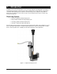
1 Introduction The DispenseJet Series DJ-100 (Figure 1-1) is a non-contact applicator providing high-speed delivery and exceptional volumetric control for various fluids, including surface mount adhesive, encapsulants, conformal coating, liquid crystal, UV adhesives, and silver epoxy. The Jet dispenses fluid either as discrete dots or a rapid succession of dots to form a stream of fluid from the nozzle as small as 100micrometer in diameter.
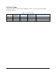
DJ-100 Jet Types Asymtek’s DJ-100 Jets have three major configurations. Table 1-1 describes all currently available models of the DJ-100. Table 1-1 DJ-100 Jet Types Jet Type 2 Amplifier Module Stroke Length Min Jet On-Time for Max Stroke Viscosity Range DJ-100 CON-100 Approx. 165 µm 250 µs Approx. 50~200,000 mPas DJ-100 NC CON-100 NC Approx. 45 µm 220 µs Approx. 50~1,000 mPas DJ-100 GH CON-100 GH Approx. 320 µm 500 µs Approx.
2 Safety Dispensing system operation involves heat, air pressure, fluid pressure, mechanical devices, electrical power, and the use of hazardous materials. Refer to the Safety section of your particular dispensing system Operations Manual prior to installing and operating your DispenseJet Series DJ-100. Safety is considered a joint responsibility between the original equipment manufacturer (Asymtek) and the end-user (owner).
Preventing Equipment and Workpiece Damage • Immediately push the EMO button on the dispensing system if the dispensing system, DJ-100, or a workpiece is in danger of being damaged. • Use standard Electrostatic Discharge (ESD) precautions when working near sensitive components. Always wear a grounding strap and connect it to the ESD ground before handling workpieces and equipment. • Perform all recommended DJ-100 maintenance procedures at the suggested intervals.
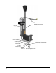
3 Operation The DJ-100 is driven by two two specially positioned piezoelectric actuators. The actuators move a rod, which is lifted or lowered. A sealing ball from resistive ceramics is fixed to the lower end of this rod. The tight fit from ceramic plate is closed by means of the sealing ball. When the sealing ball is lifted, the fluid can flow from the valve. Due to the extremely fast piezoelectric drive it is possible to achieve a dispensing frequency of up to 1000 Hz.
Fluid Pressure Line Electrical Connection Syringe Thermal Isolation Jet Serial Number Heater System Nozzle Plate Serial Number Sealing Ball O-Ring Nozzle Plate Figure 3-1 DJ-100 Exploded View 4
Rod Piezoelectric Actuators Sealing Ball (Open Position) Fluid Path Rod Piezoelectric Actuators Sealing Ball (Closed Position) Fluid Path Figure 3-2 DJ-100 Jet Operation The signal for the piezoelectric actuators is generated by the platform and amplified by the CON100 amplifier module. An additional programming module (PDA) is needed to control the jet on time for the Axiom platform only. CAUTION! The jet offers a heated fluid area. The maximum temperature is + 100°C.
Nozzle Sizes The nozzle diameter can be determined from the marking on the nozzle plate. The following nozzle diameters are available: 100µm, 150µm, 200µm, and 300µm. A 300µm nozzle is shown in Figure 3-3.
4 Installation The DJ-100 is designed for use on Asymtek’s Axiom X-1000, DispenseMate 580 Series, Spectrum S-820 Series, and Spectrum S920 Series Dispensing Systems. " NOTE For more information, refer to the manual for your particular dispensing system. Unpacking the DJ-100 Every care has been taken when packaging your DJ-100. However, we recommend that you look for obvious damage and verify contents against the packing slip. Retain the case for storage of the DJ-100 and accessories.
8. After the jet has been installed, you must adjust the Height Sensor Probe. Refer to the appropriate platform manual. 9. The DJ-100 is now connected and ready for operation.
Figure 4-2 Connection Diagram – S-920 Series " NOTE The connections in Figure 4-2 also apply to Asymtek’s DispenseMate and Spectrum S-820 platforms.
Installing/Changing a Fluid Syringe Tools and Materials Needed " • Clean Cloth and Solvent (for spills) • Syringe of Fluid to be Dispensed • 10mm Wrench or Pliers (as needed) • Appropriate Personal Protective Equipment NOTE 1. Use position controls to move the dispensing head to the front center of the dispensing area. 2. Perform a production shutdown as specified in the applicable dispensing system manual. ! If there is no syringe installed, skip to Step 6. 3.
Software Configuration Once you have installed the DJ-100 on your dispensing system, the dispensing software must be configured. WARNING! Only trained service technicians should perform this procedure. 1. Perform a system start-up as specified in the applicable dispensing system manual. 2. Start the Fluidmove software by double-clicking the Fluidmove icon desktop. 3. Select Configuration > Setup Valves from the Fluidmove Main Window. ! on the Windows The Setup Valves screen (Figure 4-3) opens.
5 Maintenance and Service Overview Performing the recommended maintenance and service procedures at suggested intervals increases the life of your DJ-100 and ensures high quality performance for every production run. Record Keeping The type of procedure performed should be recorded in maintenance records for the DJ-100 Jet. Dates, part numbers/serial numbers of replaced parts, names of technicians, and other pertinent data should be recorded.
Cleaning the Nozzle Plate and Fluid Channel CAUTION! WARNING! Each jet and its associated nozzle plate are precisely aligned at the factory and delivered as a matched assembly with identical serial numbers on the jet and the nozzle plate. Be careful not to accidentally interchange jets and nozzles when cleaning or performing maintenance. After removing the screws, do not use tools to remove the nozzle plate from the jet. Using tools can cause serious damage.
Inspecting the DJ-100 for Wear Before start of production, the DJ-100 ceramic ball, valve seat, sealing valve body / rod (white o-ring), & rod should be inspected to ensure all particulate and any cured fluid is properly removed. It is critical to the lifetime of the DJ-100 assembly to remove cured fluid, debris or any particulate from the mating surfaces between ball tip and valve seat.
6 Troubleshooting Overview This section will help you determine the origin of problems you may experience with your valve and provide the recommended corrective actions. If you experience problems that are not listed in this section, or continue experiencing the problem after trying the suggested corrective actions, please contact Asymtek Technical Support for more advanced fault diagnostics.
Troubleshooting the Jet Basic troubleshooting and suggested recovery measures are presented in Table 6-1. Due to variances in production environment and operational conditions, not every possible problem can be addressed. TIPS To quickly identify problems, look for obvious signs such as burnt, missing, damaged, or loose parts as well as obstructions and spills. Obvious uncharacteristic heat, noise, vibration, odor, or movement can also help to isolate problems.
Status Signals and Fault Codes The LEDs on the front of the CON100 control unit indicate status signals as well as faults.
7 Additional Information Recommended Facility Items In addition to the supplied accessories and tools, it is recommended that the following items be available at your facility: • Personal Protective Equipment recommended in applicable MSDS • Bench Lamp and Magnifier Set • Ultrasonic Cleaning System • Airgun and compressed, dry air • Appropriate fluid collection and disposal container • Solvent appropriate for the fluid used • O-ring type lubricant • Disposable towels, cleaning swabs and bru
Spares and Accessories Table 7-1 lists available spares and accessories. You may order entire kits or by individual part number. Table 7-1 Spares and Accessories Part Number Part Description Description 7218366 124520 48-8105 58-0036 58-0038 7214868 7218364 7218387 7218413 7218415 7218442 7218443 901916 901922 901923 901924 901935 KIT, CLEANING DJ-100 SCREWDRIVER,#0 PHILIPS TOOL,SEAL REMOVAL,PLASTIC SWAB,COT,RD.TIP,6”WD,100/PKG SWAB,MINI,COT,WD.HNDL 100/PKG BRUSH,BOTTLE,.
Table 7-1 Spares and Accessories (continued) Part Number 20 Part Description 7218387 ASSY, FEED TUBE, DJ-100,PKG/25 7218444 ASSY, FEED TUBE UV, DJ-100,PKG/25 7218355 DJ-100 (300µm nozzle) 7218357 DJ-100 NC (150µm nozzle) 7218359 DJ-100 GH (300µm nozzle) 7218390 DJ-100 (200µm nozzle) 7218393 DJ-100 GH (200µm nozzle) 7218410 DJ-100 NC (100µm nozzle) Description
Sample Application Settings See Table 7-2 and Table 7-3 for a list of settings that affect DJ-100 performance. Values are application dependent. Refer to the Fluidmove User Guide or Online Help for detailed software instructions. Values are saved in the Fluidmove configuration, fluid, heater, and program files. A column is provided for you to record your current settings.
8 Specifications The specifications below are intended as a convenient reference for personnel involved with installation, operation, and maintenance of the DJ-100. This section contains the technical specifications for the DJ-100 Jet. If you have any questions about these specifications or jet performance, contact Asymtek Technical Support or your authorized distributor.
DJ-100 Electrical Interface Assignment 28-pin female CPC connector 3 8 2 7 1 6 5 4 14 13 12 11 10 9 20 19 18 17 16 15 25 24 23 22 28 27 26 21 Pin Signal Pin Signal 1 UNUSED 15 UNUSED 2 UNUSED 16 UNUSED 3 UNUSED 17 UNUSED 4 +24V 18 UNUSED 5 NEEDLE_HEAT1/ 19 PICO_RX_TX 6 RTD1_RETURN 20 GND/A 7 RTD1_SENSE 21 UNUSED 8 UNUSED 22 UNUSED 9 UNUSED 23 UNUSED 10 UNUSED 24 UNUSED 11 UNUSED 25 UNUSED 12 UNUSED 26 UA 13 PE 27 UNUSED 14 E
9 Illustrated Parts List Table 9-1 identifies components referred to in Figure 9-1. The item numbers associated with the description correspond to the callout numbers in the illustration. " NOTE Before attempting to replace any parts, please review the precautions in the Safety section. Table 9-1 Illustrated Parts List 24 Item No. Part No.
9 7 10 11 12 1 2 3 4 5 6 8 13 14 15 21 22 23 24 19 20 18 16 17 Figure 9-1 DJ-100 Illustrated Parts List 1
Asymtek Headquarters 2762 Loker Avenue West Carlsbad, CA 92010-6603 USA Tel: (760) 431-1919 1-800-ASYMTEK (1-800-279-6835) P/N 7218011, Revision A © 2008