
Instruction Manual


DG-1000 Dispenser
18
1998 Nordson Corporation
All rights reserved
107 156C
Issued 11/98
Manual 12-35
CAUTION: Handle O-rings and seals carefully. If O-rings or
seals are damaged, leakage or premature dispenser failure
may occur.
CAUTION: Protect the solenoid valve from contact with coating
material or solvent. Contamination could cause solenoid failure.
NOTE: Assemble the dispenser on a flat surface.
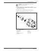
See Figure 5.
1.Place the dispenser bodies on their backs. Mate the upper body (15)
with the lower body (14) and secure with the fillister screws (5).
2.Apply Teflon tape to the threads of the male connector (4). Install the
connector into the lower body (14).
3.Install a U-cup seal (6), spring side facing out, into the lower
body(14). Using the ring and seal insertion tool, carefully seat the
seal into the body.
4.Place the O-ring (7), into the lower body (14).
5.Install a U-cup seal (6), spring side facing out and up, into the upper
body (15). Using the ring and insertion tool, carefully seat the seal
into the body.
6.Install the fitting (16) and plug (3) on the upper body (15).
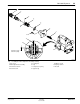
1.Apply conductive grease to the heater extension (9).
2.Lubricate the O-ring (8) with Parker O-ring lubricant or an equivalent
lubricant. Install the O-ring on the heater extension (9).
3.Place the heater (10) on the heater extension (9). Rotate the heater
extension assembly to spread the conductive grease evenly and
remove air pockets.
4.Install the heater extension assembly on the upper and lower body
assembly and secure using the cap head screws (11).
5.Install the nozzle gasket (13) and nozzle (12).
Install the solenoid valve (2) on the upper body (15) and secure using
socket head screws (1).
7. Assembly
Dispenser Bodies
Heater
Solenoid Valve