Century® Series C-740/C-741 Dispensing System Quick Operations Manual
NOTICE This is an Asymtek publication which is protected by copyright. Original copyright date 2006. No part of this document may be photocopied, reproduced, or translated to another language without the prior written consent of Asymtek. The information contained in this publication is subject to change without notice. Manuals on the Internet For the convenience of Asymtek customers and field service representatives, copies of Asymtek manuals can be downloaded from: http://www.asymtek.com/support/manuals.
TABLE OF CONTENTS 1 Introduction ......................................................................................................................................... 1 Overview ............................................................................................................................................... 1 Safety First ............................................................................................................................................ 1 Basic System Description...
Maintenance....................................................................................................................................... 51 Overview ............................................................................................................................................. 51 Safety First .......................................................................................................................................... 51 Hazardous Materials ..............................
1 Introduction Overview Congratulations on your choice of the Century C-740/C-741 Series Dispensing System! This manual is intended primarily as a reference for production operators. However, others unfamiliar with Asymtek products may also find this manual useful as a general introduction to the system. The Century C-740/C-741 Series Dispensing Systems are designed to meet the diverse needs of the conformal coating market.
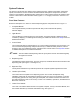
System Features The figures in this section show features of the dispensing system. Callouts locate major components, options, and switches. The item numbers associated with the descriptions correspond to the callout numbers in the illustration. Detailed operating instructions for some of these features are treated in other sections of this manual. Unless otherwise noted, Figures 1-1 to 1-8 apply to both the C-740 and C-741 models.
2 3 1 4 2 5 7 3 C-740 6 4 1 5 7 C-741 6 Item Description Item Description 1 Computer Monitor 5 Keyboard Tray (keyboard and mouse) 2 Light Beacon 6 Leveler (foot pad) 3 Control Panel (Figure 1-2) 7 Lower Front Cabinet (Figure 1-5) 4 Dispensing Area (Figure 1-3) Figure 1-1 C-740/C-741 Front View Introduction 3
Control Panel Below are descriptions of C-740/C-741 Series Dispensing System Control Panel buttons as shown in Figure 1-2. " NOTE Refer to the Operation section for detailed descriptions of all Control Panel buttons and functions. 1. Start/Stop Buttons The Start and Stop buttons are push buttons located on the Control Panel. They control the power to the dispensing system.
Dispensing Area Below are descriptions of C-740/C-741 Series Dispensing System components shown in Figure 1-3. 1. Solvent Cups The Century C-740 conveyorized system has two 125 ml stainless steel cups that are installed on separate brackets mounted to the front Conveyor rail. One cup holds solvent for cleaning the dispensing needle. A second cup is used for the purging of conformal coating fluid. The solvent cups can be positioned as desired by the operator on the C-741 batch dispensing system. 2.
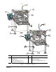
Dispensing Area Close Up Below are functional descriptions of C-740/C-741 Series Dispensing System components shown in Figure 1-4. 1. Board Sensor (C-740) Mounted on the Conveyor rail within the dispense zone, the Board Sensor detects the presence of a workpiece entering the system. The signal is sent to the Conveyor Controller, which halts Conveyor motion and lowers Stop Pins to hold the part in place for dispensing. 2. Chain Conveyor (C-740) A chain Conveyor is standard on the C-740 Dispensing System.
1 3 2 C-740 with Chain Conveyor 4 5 6 C-741 with Adjustable Tooling Rails Item Description C-741 with Tooling Plate Item Description 1 Board Sensor 4 Fluid Dispensing Applicator 2 Chain Conveyor (C-740) 5 Tooling Plate 3 Stop Pin 6 Adjustable Tooling Rails Figure 1-4 C-740/C-741 Dispensing Area Close-up Introduction 7
Lower Front Cabinet Below are descriptions of C-740/C-741 Series Dispensing System components shown in Figure 1-5. 1. Computer The Computer System is used to create and run dispensing programs with the Asymtek Easy Coat for Windows XP (ECXP) dispensing software. 2. Conveyor Controller Module (C-740) The Conveyor Controller module monitors the SMEMA interface and controls the Conveyor indexing operations. The inputs and outputs are used for sensors, Stop Pins, Board Pins, and operation of the Conveyor.
Computer Below are functional descriptions of the system computer front panel controls shown in Figure 1-6. The numbers associated with the descriptions correspond to the callout numbers in the illustration. 1. CD-ROM Drive Press the button below and to the right of the disk tray to insert or eject a disk. 2. 1.44 MB 3.5-inch Disk Drive The computer has at least one 3.5-inch, 1.4 MB disk drive. Insert disks through the drive door flap. Press the small button on the lower right to eject a disk. 3.
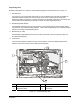
Rear View Features Below are descriptions of C-740/C-741 Series Dispensing System components shown in Figure 1-7. 1. Main Air Regulator The Main Air Regulator regulates air pressure supplied to the dispensing system through the Main Air Inlet. 2. Main Air Inlet The Main Air Inlet connects the Century Series Dispensing System to your facility air supply. 3. Main Air Gauge The Main Air Gauge indicates the air pressure to which the Main Air Regulator is set.
1 2 3 4 5 10 6 9 7 8 Item Description Item Description 1 Main Air Regulator 6 Low Fluid Sensor 2 Main Air Inlet 7 Fluid Reservoir (5 gallon) 3 Main Air Gauge 8 Fluid Reservoir (1 gallon) 4 Air Filter and Water Trap 9 Manual Material Change Over Option 5 Exhaust Vent Duct 10 Fluid Filter Figure 1-7 Rear View (with Material Changeover Option) Introduction 11
Lower Rear View Below are descriptions of the C-740/C-741 Series Dispensing System components shown in Figure 1-8. 1. Main Power Inlet The Main Power Inlet connects the Main Power Cord from the facility power source to the dispensing system. 2. Main Power Circuit Breaker The Main Power Circuit Breaker controls all electrical power to the entire system including the dispensing system, Computer, and Computer Monitor. 3.
4 3 5 6 2 1 7 8 Item Description 1 Main Power Inlet 2 Main Power Circuit Breaker 3 Power Manager Module 4 Tri-Mode Swirl Box (Optional) 5 Conveyor Controller Module (C-740) 6 Computer 7 SMEMA Connector (upstream) 8 SMEMA Connector (downstream) Figure 1-8 Lower Rear View Introduction 13
Right Rear View (Close-up) Below are descriptions of C-740/C-741 Series Dispensing System components shown in Figure 1-9. 1. Stop/Clamp Air Gauge (C-740) The Stop/Clamp Air Gauge indicates the air pressure to which the Stop/Clamp Air Regulator is set. The recommended setting is 206 to 275 kPa (30-40 psi). 2. Stop/Clamp Air Regulator (C-740) The Stop/Clamp Air Regulator controls the air pressure supplied to the Stop Pins and Board Pins on the Conveyor. 3.
2 Safety Overview This section is intended to provide basic safety information necessary for operating and servicing the Century C-740/C-741 Series Dispensing System.
Basic Safety Precautions and Practices Compliance with the following recommended precautions and practices will prevent personal injury or damage to property during Century C-740/C-741 Series Dispensing System operation and maintenance. WARNING! CAUTION! Failure to comply with any of the safety recommendations could cause serious injury to the user or damage to the dispensing system.
• Where volatile organic compound (VOC) emissions can exceed safe limits, facility ventilation and filtration systems must be operational. • Provide adequate space around the dispensing system to allow for movement of maintenance and service personnel. Allow space for access doors and service panels to open fully. • Make sure all facility power sources are safely grounded. • Routinely inspect all air hoses and electrical cables for damage.
Safety Warning Labels WARNING! CAUTION! Comply with all safety warning labels or serious injury to personnel or damage to the dispensing system may occur. Worn or damaged labels should be replaced with new labels having the same part number. Warning labels on your Century C-740/C-741 Series Dispensing System point out areas where personnel must use extreme caution to prevent serious injury and property damage.
1 2 1 3 Front View 2 2 Rear View Item Description 1 General Warning 2 Electrical Warning 3 General Warning (on top-side of gauge) Figure 2-1 Safety Warning Labels, Safety 19
Emergency Shutdown Your Century C-740/C-741 Series Dispensing System features an Emergency Machine Off (EMO) button that the operator or service technician can use to immediately stop all dispensing operations in case of emergency. This feature helps prevent injury to personnel and damage to the dispensing system and workpieces being processed. The EMO button is located on the Control Panel on the front of the dispensing system (Figure 2-2).
Emergency Shutdown Situations As a minimum, activate the EMO in the following situations: WARNING! CAUTION! In an emergency, failure to completely shut down power to the dispensing system with the EMO can cause serious injury to the user and/or damage to the dispensing system. • If anyone is in immediate danger of being injured by moving parts, hazardous materials, or electrical shock. • If valuable dispensing system components or the workpieces are in danger of being damaged.
Integrated Safety Systems The C-740/C-741 Series Dispensing Systems have a built-in safety system that automatically protects personnel from being injured by movement of the Dispensing Head and Conveyor.
CAUTION! Do NOT use the Interlock OFF mode during normal operation. Use OFF mode only when servicing or programming the dispensing system. ON Mode When the Interlock is ON (I) and a dispensing program is running, opening the front doors stops all dispensing motion and all position references are lost. This Interlock shutdown condition is indicated by a red System Status Indicator LED on the Control Panel (Figure 2-3) and by a red light on the Light Beacon.
Interlock Recovery Light The Interlock Recovery Light (Figure 2-5) is located on the Control Panel and is labeled Interlock Recovery. When the light is ON, you can safely access the inside of the dispensing area. When the light is OFF, accessing the inside of the dispensing area will cause a non-recoverable interlock shutdown to occur.
Light Beacon Located at the top right corner of the system, the Light Beacon is a device that displays system status. The Beacon has four different colored lights that can be constantly ON or flashing and has an audible alarm. The colors on the Light Beacon correspond with the System Status LED’s on the Control Panel. See Table 2-2 for an explanation of each color indication. The Light Beacon can be custom configured to respond to the I/O states of customer equipment.
Table 2-2 Light Beacon Color Indications Beacon Color Dispenser Status ALERT • Close doors or remove obstruction, or change INTERLOCK to “0” position. • Press DISPENSER STATUS RESET. • Press FIND HOME. • Select the proper Interlock Mode for your application. 2. System is in an abort state. • Restart the program. 3. INTERLOCK at “I” position, Low Pressure Sensor has been activated. • Check your facility air supply. • Increase ventilation. • Press DISPENSER STATUS RESET.
3 Operation Overview Before operating your Century C-740/C-741 Dispensing System, it may be helpful to familiarize yourself with the basics of how the system works.
Dispensing Operations All dispensing operations take place in the workcell, also referred to as the dispensing area. The workcell contains a robot and a fluid dispensing applicator mounted on the robot tool arm. Robot Concepts Home The home position of the robot is a known position within the workspace defined by X, Y, and Z coordinates. It is generally located at the front left of the workcell. Tool A tool consists of a fluid dispensing applicator and nozzle.
Coordinate Systems All positioning in the workcell is done with reference to sets of position coordinates, called Reference Frames. As you face the front of the workcell, the X-axis is left to right, the Y-axis is front to rear, and the Z-axis is up and down. Three different sets of Reference Frames are used: Robot Reference Frame, Product Reference Frame and Pattern Reference Frame.
Conveyor Operations Chain Conveyor (C-740) The chain conveyor, standard on the Century Series C-740 Dispensing System, transports the workpiece into and out of the dispensing system. Operation of the conveyor is automatic during production runs. An optical sensor detects the part as it arrives, triggering the Conveyor Controller Module to activate the Stop Pin to stop the part at the correct location. Board pins in the dispense zone secure the part in place during fluid dispensing.
1 2 3 Item Description 1 Conveyor Rails 2 Conveyor Adjustment Clamp 3 Hand Crank Figure 3-2 Manual Conveyor Width Adjustment Operation 31
Control Panel The following operational controls are located on the Control Panel (Figure 3-3).
Power Buttons Table 3-1 Power Buttons Button/Switch Appearance Function Located at the right end of the Control Panel, the large, red Emergency Machine OFF (EMO) button cuts electricity to the Power Manager and stops all system motion. EMO Button Pressing the EMO vents all pressure in the pneumatic system, de-energizes the robot motors, and cuts power to all system components except the Computer and Monitor.
Motion Controls Table 3-3 Motion Controls Button/Indicator Z-AXIS Function Moves the Dispensing Head up in small* increments. Moves the Dispensing Head down in small* increments. Moves the Dispensing Head up in large** increments. Moves the Dispensing Head down in large** increments. " TEACH NOTE The Z-Axis arrows are non-functional for the conveyor. TEACH lets you set a desired point on the dispensing surface when prompted by the Easy Coat program.
Table 3-3 Motion Controls (continued) Button/Indicator Function Dispensing Head Response (XY-Axis) Conveyor Response (XY-Axis) Moves the Dispensing Head to the back in small* increments. Moves the Dispensing Head to the front in small* increments. CONVYR ENABLE ROBOT ENABLE Moves the Dispensing Head to the right in small* increments. Moves the Conveyor to the right in small* increments. Moves the Dispensing Head to the left in small* increments. Moves the Conveyor to the left in small* increments.
System Status Controls Table 3-4 System Status Controls Button/Indicator CONVEYOR STATUS V PAUSE RESET INTERLOCK RECOVERY INTERLOCK Function CONVEYOR STATUS has two buttons. PAUSE halts the Conveyor. The PAUSE LED lights up to indicate that the Conveyor has been paused. Press PAUSE again to resume Conveyor movement. Press RESET to clear the Conveyor Controller after a fault condition has occurred.
Pneumatic Regulators and Gauges The C-740/C-741 Series Dispensing Systems have the following pneumatic regulators and gauges: • Main Air Regulator and Gauge • Conveyor Stop/Clamp Air Regulator and Gauge • Fluid Pressure Regulator and Gauge The Main Air and Conveyor Stop/Clamp regulator controls are located at the rear of the system (Figure 3-4 and Figure 3-5). The Fluid Regulator control is a black knob extending down from the roof of the dispensing area (Figure 3-6).
Main Air Regulator and Gauge The main air inlet provides regulated air pressure to the dispensing system from your facility air source. You can adjust the main air pressure with the Main Air Regulator. The recommended pressure from the facility air supply to the dispensing system is 85 to 90 psi (586 to 620 kPa). To adjust the main air pressure: 1. Verify that the facility air supply is connected to the main air inlet. 2. Locate the Main Air Regulator at the rear of the dispensing system (Figure 3-4).
Conveyor Stop/Clamp Air Regulator and Gauge Located on the right rear of the dispensing system next to the main air inlet, the Stop/Clamp Air Regulator and Gauge controls air pressure supplied to the stop pins and board pins (chain conveyor) and/or bar clamps. The recommended air pressure is 30 to 40 psi (206 to 275 kPa). " NOTE If air pressure is too high, parts may be damaged. If pressure is too low, the stop pins, board pins and bar clamps will not work.
Fluid Pressure Regulator and Gauge The Fluid Pressure Regulator controls the pressure of the fluid reservoir for the SC-205 Non-Circulating Film Coater and the SC-200 Slim Swirl Applicator. For the SC-105HS High Speed Film Coater, this regulator controls the pilot pressure to the pilot operated fluid regulator on the rear of the dispensing system. For more details on how the air is used for fluid pump operation and recommended pressure setting, refer to the manual for your specific fluid pump.
System Startup/Shutdown These following procedures are offered as general recommendations and suggestions when starting and/or shutting down your Century C-740/C-741 Series Dispensing System. Your actual start-up and shutdown procedures may vary. WARNING! Only authorized service technicians or process engineers should connect power cables to the power source. Operators should not attempt to make electrical connections.
To Start ECXP: 1. " Double click the ECXP icon on the Windows desktop. ! As an alternative, you may click on the Windows Start menu and select Programs > ECXP to start the ECXP software. ! The Dispenser will find Home in the Z-Axis, Y-Axis, and X-Axis, respectively. ! The ECXP Operator Screen shown in Figure 3-7 will open. NOTE The Operator Screen will vary slightly if the software is configured for a C-741 Series Dispensing System. Figure 3-7 Starting ECXP " 2.
Shutdown Emergency Shutdown In case of an emergency or malfunction, press the EMO button. The EMO is the large red button on the Control Panel. Refer to the Safety section for important information concerning emergency shutdown. WARNING! Power is still available to the power supply and to the Power Manager after an Emergency Shutdown. To fully remove power to the system, all power cords must be disconnected. Routine Shutdown Routine shutdown may vary depending on your particular requirements.
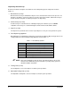
Daily Routine Procedures Table 3-6 contains a brief description and instructions for routine procedures that should be performed on a daily basis before and after operating the dispensing system. Table 3-6 Daily Routine Procedures Procedure Description STARTUP Clean Fluid Filter Check the fluid filter and clean if necessary. Refer to “Cleaning the Fluid Filter”. Check Main Air Pressure Ensure that the main air pressure is properly adjusted.
Characterization " NOTE A characterization must be performed for each tool and each coating material used or as required to ensure quality and consistent dispensing. Many variables, such as material type, temperature, viscosity, substrate type, robot velocities, and dispenser response times affect the coating process. Characterization improves coating placement accuracy and repeatability. The Characterization Wizard helps you adjust program values to compensate for these variables.
2. Click Clear Positions and then click OK to confirm. ! If you have performed a characterization before, the old test area coordinates are used unless you clear them. 3. Click Next. 4. Click Yes when prompted to teach the substrate height. 5. Teach the substrate height. a. Install a nozzle on the Fluid Dispensing Applicator and lower the tool until the tip just touches the substrate. b. Click Teach Z c. Click OK 6. Enter the dispense height.
10. Position the tool tip over the left intersection of the dotted lines and click Next. 11. Position the tool over the right intersection of the dotted lines and click Next. 12. Position the tool tip over the right dotted line and the back line and click Next. ! 13. Remove any teaching devices before continuing. Click Next. ! The Wizard will now apply three stripes of material to the test area (See Figure 3-10).
Loading a Program Programs can be loaded from both the ECXP Operator Screen (Figure 3-11) and the ECXP Edit Screen Refer to the Century C-740/C-741 Installation, Operations, and Maintenance Manual for instructions on loading a program from the Edit Screen. To load a program from the Operator Screen: 1. If a program is currently running, click on the Stop ! 2. button. Production stops after the currently loaded product is coated.
Running a Program Programs can be run from both the ECXP Operator Screen (Figure 3-12 and Figure 3-13) and from the ECXP Edit Screen. Refer to the Century C-740-C-741 Installation, Operations, and Maintenance Manual for instructions on running a program from the Edit Screen. Operator Screen To run a program from the Operator Screen (C-740 Conveyorized System): 1. Load the program you want to run as described in “Loading a Program” previously in this section. 2. Click on the Start button. 3.
To run a program from the Operator Screen (C-741 Batch System): 1. Load the program you want to run as described in “Loading a Program” previously in this section. 2. Load a new product (board or carrier) into the fixture. 3. Click on the Start button and then on the Run Product button.
4 Maintenance Overview Performing recommended maintenance procedures increases system life and ensures high quality dispensing performance for every production run. This section covers the following operator-level procedures: Filling the Fluid Reservoir Changing Material/Flushing Fluid System Emptying the Water Trap Cleaning the Fluid Filter Refer to the Century C-740/C-741 Installation, Operations, and Maintenance Manual for detailed information on all recommended maintenance procedures.
Filling the Fluid Reservoir CAUTION! Make sure to observe the fluid level indicator. Never let the dispensing system run out of fluid as this may damage the fluid applicator. To fill the Fluid Reservoir: 1. Turn the Reservoir Air Pressure Pneumatic Switch to the OFF (0) position. 2. Relieve residual pressure in the Fluid System by opening the Fluid Pressure Relief Valve on the Fluid Reservoir. 3. Open the lid and check that the reservoir is clean and free from foreign materials.
Changing Material/Flushing Fluid System To change material and flush the Fluid System: 1. If applicable, turn off the heater and allow the fluid to cool for at least fifteen minutes. 2. Reduce fluid air pressure to 7 psi (48 kPa). ! 3. Refer to “Pneumatic Regulators and Gauges” in the Operation section for instructions on adjusting fluid pressure. Open and drain the Fluid Applicator. ! Refer to the manual for your specific Fluid Applicator for instructions. 4.
Emptying the Water Trap Moisture from the outside air can condense in the pneumatic system. The Water Trap collects this condensed moisture. You must empty it monthly or whenever it is full. WARNING! Do not remove the steel bowl guard protecting the Water Trap. The bowl is made of polycarbonate plastic, which could rupture if the inside or outside of the bowl is exposed to chemicals incompatible with polycarbonate. To empty the Water Trap: 1. Locate the Water Trap (Figure 4-2) at the rear of the system.
Cleaning the Fluid Filter To clean the Fluid Filter: 1. Turn the Reservoir Air Pressure Pneumatic Switch to the OFF (0) position. See Figure 4-3. 2. Relieve residual pressure in the Fluid System by opening the Pressure Relief Valve on the Fluid Reservoir. WARNING! 3. To prevent eye injury or irritation, wear safety goggles while performing this procedure. Unscrew the Fluid Filter cap. The Fluid Filter is located inside the housing. ! 4.
Asymtek Headquarters 2762 Loker Avenue West Carlsbad, CA 92010-6603 USA Tel: (760) 431-1919 1-800-ASYMTEK (1-800-279-6835) P/N 7209770, Revision A ©2006