
Instruction Manual


4-12 Installation
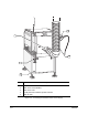
4.9 Pneumatic Connections
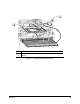
The C-740/C-741 Series Dispensing System requires 85 l/min (3 scfm) of clean, dry air delivered through
a 12.7 mm (0.5 inch) pipe or hose at 80 to 100 psi (551 to 689 kPa). Connect the air supply to the ¼ -inch
NPT quick-disconnect fitting at the Main Air Inlet (Figure 4-5).
" NOTE The maximum air supply pressure should not exceed 100 psi (689 kPa).
WARNING! CAUTION!
All system pneumatic connections should be checked before the main air
is connected.
Refer to Appendix A for C-740/C-741 Series Dispensing Systems pneumatic diagrams.
4.10 Electrical Connections
The dispensing system requires 1 kw of single-phase power at 100, 120, 220, or 240 VAC.
" NOTE Refer to Section 11 - Specifications for more information on electrical requirements.
Contact your Asymtek representative for your particular system requirements.
Refer to Appendix B for C-740/C-741 Series Dispensing Systems electrical diagrams. Dispensing system
electronic connections are detailed in Appendix D.
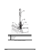
4.11 Exhaust Connection
The dispensing system requires a 15.3 cm (6 inch) diameter exhaust duct capable of drawing a minimum
of 0.28 m
3
/s (600 scfm) air at 25.4 mm (1 inch) water column (w.c.) static pressure.
" NOTE Refer to Section 11 - Specifications for more information on exhaust requirements.
Contact your Asymtek representative for your particular system requirements.