
Instruction Manual

4-6 Installation
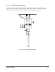
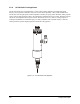
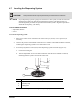
4. Place a level in the center of the left Y-rail of the Conveyor.
5. Observe the position of the bubble within the level’s window. The bubble should be centered,
indicating the dispensing system is level from side-to-side.
6. If necessary adjust the Levelers (feet) of the dispensing system as described in Steps 3a
and 3b.
7. Place a level in the center of the right Y-rail of the Conveyor.
8. Observe the position of the bubble within the level’s window. The bubble should be centered,
indicating the dispensing system is level from side-to-side.
9. If necessary adjust the Levelers (feet) of the dispensing system as described in Steps 3a
and 3b.
10. When the dispensing system is level, lock the footpad adjustment firmly in place by
tightening the locking nut.
11. Align the dispensing system so that the Conveyor is parallel to the mating conveyer, if the
unit is integrated in a production line.
4.8 Component Installation
Your Century C-740/C-741 dispensing system is assembled at the Asymtek factory. However, to protect
components during shipment, some are packaged in the accessories crate to be installed after arrival.
Once installed, these components are functionally tested along with the rest of the system as detailed in
Section 5 - Power-up and Testing.
4.8.1 Installing the Fluid Dispensing Applicator
The Fluid Dispensing Applicator should have already been installed on your dispensing system at the
Asymtek factory. If it has not been installed, a trained service technician should install it in accordance
with the appropriate fluid applicator manual.
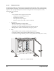
4.8.2 Installing the Monitor
CAUTION! Make sure all power sources are disconnected before performing this procedure.
This procedure should only be performed by a trained service technician.
Tools and Materials Needed:
• Monitor (P/N 07-6002-00) • Monitor Computer Cable
• 1/8-inch Hex Key • Monitor Power Cable
" NOTE All materials are included in the accessories crate that accompanied your dispensing
system.