
Instruction Manual


D-8 Appendix D – Dispensing System Electronics
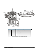
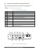
D.8 Rear Connections
All connections to the Century Series C-740 dispensing system are accessible from the rear of the unit
and shown in
17HFigure D-2.
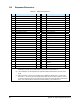
18HTable D-5 gives a brief description of each connection.
Table D-5 Century Series C-740 Dispensing System Rear Connections
Item Feature Description
1 ELEC 0 Not used
2 ELEC 1 Control cable connector (gun drivers, CPX left, CPX right,
pressure switch)
3 ELEC 2 Optional fluid sensor
4 DC POWER 13-pin D-shell connector for DC power
5 ELEC 3 Light tower
6 MTR/VHP Not used
7 ELEC 4 Safety interlock cable connector (vent switch, front door
interlocks, low air pressure switch)
8 ELEC 5 Not used
9 Drivers Accessories (i.e., laser pointer)
10 ELEC 6 Main connector for robot controller interconnect RS-232
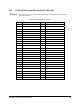
11 FANS Fan control connector (not used)
12 INTERLOCK Connector for front door interlocks
13 IN 1 External I/O for optional use – provides access for additional
options to the dispensing system such as 24 Vdc source for
external use
14 IN 2 External I/O for optional use
15 IN 3 External I/O for optional use
16 ELEC 9 Z-axis cable connector
17 OUT 1 External I/O for optional use
18 OUT 2 External I/O for optional use
19 P 19 Pneumatic connection
20 P 20 Pneumatic connection
21 P 21 Pneumatic connection
22 P 22 Pneumatic connection
23 Tilt Regulator Tilt Air Regulator - factory preset to 40 psi.
24 P 24 Pneumatic connection
25 P 23 Pneumatic connection
26 P 18 Pneumatic connection
27 P 17 Pneumatic connection
28 P 1 through 16 Pneumatic connections
29 Power Input Manager VAC power input connector and fuse holder – toggle switch turns
dispensing system ON/OFF