
Instruction Manual


D-4 Appendix D – Dispensing System Electronics
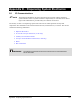
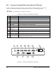
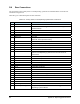
D.4 Auxiliary I/O Connector Pinouts
Pin 1 on the connector has a shorter retention tab. Pin 1 of the associated PC mounted mating connector is
to the right, when facing the back of the dispensing system. Use Asymtek connectors P/N 55-5185 (2
pin), 55-5906 (3 pin), and 55-5908 (4 pin).
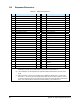
Input activation requires 5 mA to be sunk to RETURN. Output transistors are 6 mA capable. Refer to
Table 8-2 for bit mapping information.
INTLK – [1] +24 Vdc switched, [2] Anode, [3] Cathode, [4] Return (connect cathode to return to activate
machine interlock).
IN 1 – [1] CATC0, [2] RETURN, [3] +24 V_SWITCHED
IN 2 – [1] CATC1, [2] RETURN, [3] +24 V_SWITCHED
IN 3 – [1] CATC2, [2] RETURN, [3] +24 V_SWITCHED
OUT 1 – [1] COLC6, [2] EMC6
OUT 2 – [1] COLC7, [2] EMC7
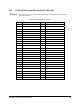
The expanded I/O has three 26-position D-sub I/O connectors, accessible in the top right inside corner of
the dispensing system. Port A, located closest to the back of the dispensing system is used in this
example. Substitute “B” or “C” for the other I/O ports.
‘CATA0’ (‘CAT’ ‘A’ ‘0’-CAT=> cathode, A=> port A, 0=> bit zero) is the cathode of the diode in an
opto-coupled diode and transistor. The transistor activates an input on the system data bus, in this case bit
0 on port A.
For the diode to properly turn on the transistor, 2 mA of current must be drawn through it by making a
connection to the IG (isolated ground) pin.
Current is limited by a resistor in series with the diode, pulled up to isolated 5 Vdc.
‘COLA1’ and ‘EMA1’ are the open collector and emitter connections to a transistor which is activated by
an opto-coupled diode, which in this case is turned on with output bit 1 in port A.
Each output has a 6 mA drive capability.
STOP-K is the cathode of an opto-coupled input diode, activation of which will place the machine into a
stopped state.
Ports A, B and C have the same connection scheme and capabilities.
"NOTE On the 60-0255-00 PCA, pin 9 on port B is connected to a STOP-K input.