
Instruction Manual


D-2 Appendix D – Dispensing System Electronics
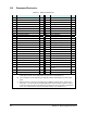
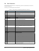
D.2 Dispenser Electronics
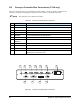
Table D-1 Dispenser Electronics
In# Function Note Out# Function Note
DA 0 Purge Button DA 0 Rotate
DA 1 DA 1 Fluid B, C
DA 2 DA 2 Fluid High Pressure/Tilt C
DA 3 Low Fluid Sensor A DA 3 Fluid High Pressure (SC-300) C
DA 4 Needle Sensor DA 4 Toggle C
DA 5 Conveyor Fault DA 5 DV-0X Valve On
DA 6 Recoverable Interlock DA 6 Assist B, C
DA 7 Rotate Home DA 7 Assist High Pressure C
DB 0 Low Pressure Sensor DB 0 Red Light Steady
DB 1 DB 1 Yellow Light Steady
DB 2 DB 2 Blue Light Steady
DB 3 Pinning Sensor DB 3 Red Light Flashing
DB 4 Stop Sensor DB 4 Yellow Light Flashing
DB 5 DB 5 Blue Light Flashing
DB 6 DB 6 Audible Alarm
DB 7 DB 7 Tilt Retract
DC 0 External Input – 1 DC 0 PLC Conveyor (Ready)
DC 1 External Input – 2/LFWC Sensor B DC 1 PLC Conveyor (Production Mode)
DC 2 External Input – 3/LFWC Sensor A DC 2 PLC Conveyor (Initialize)
DC 3 Rotate On Sensor DC 3 PLC Conveyor (Invert)
DC 4 Rotate Off Sensor DC 4 LFWC Set Threshold
DC 5 PLC Conveyor (Board Available) DC 5 Laser Pointer/LFWC Power On
DC 6 PLC Conveyor (Conveyor Ready) DC 6 External Output – 1/LFWC Step
DC 7 DC 7
External Output – 2/LFWC
Direction
AUX 1 Not Connected AUX 1 Index Request
AUX 1 Conveyor Busy AUX1 Not Connected
NOTE: A) The low fluid sensor requires a jumper to be added on the I/O-Acc. PCA to enable its operation.
Unlike other input bits, it is normally active and goes off to indicate fluid is low.
B) The indicated bits can be disabled by the applicator ON/OFF button/LED on the front control
panel.
C) Solenoid outputs on the 15-pin D-sub have driver capability as follows: DA4 – 500 mA. DA-1,
DA-2, DA-3 – 1A. Drivers are not protected against short circuits or being overdriven. A 63 W
continuous maximum draw from all solenoids, including those driving pneumatics (rated at 6 W
each). A 87 W peak draw for less than 60 seconds with duty cycle of less than 10.