
Instruction Manual


Appendix A - Pneumatic Diagrams A-1
Appendix A - Pneumatic Diagrams
A.1 Overview
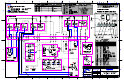
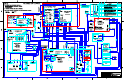
This appendix contains block diagrams that describe the Century C-740/C-741 Series Dispensing System
pneumatic system. The diagrams may help in understanding dispensing system operation and aid in
troubleshooting. The diagrams included in this appendix are described in
Table A-1.
"NOTE The drawings included in this appendix are the latest revision in effect at the time
of publication. Contact Asymtek Technical Support to verify that you are using the
current revision.
A.2 Safety First
Use of engineering drawings to disassemble, service, and reassemble the dispensing system promotes
good safety practices only when used in conjunction with the precautions in Section 2 - Safety and other
sections of this manual.
CAUTION! Only Asymtek-trained service technicians should perform troubleshooting,
servicing, and parts replacement.
A.3 List of Pneumatic Diagrams
Table A-1 Pneumatic Diagram
Drawing Number Title
194401PD Pneumatic Diagram, C-740/C-741