
Instruction Manual


Parts Replacement 10-7
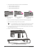
10. Bring the two ends of the chain one chain-link length apart (15HFigure 10-7).
11. Insert master link’s male link into both ends of the chain so that pins are pointing outboard
(
16HFigure 10-7).
12. Install master link’s female link onto both male link’s pins (
17HFigure 10-8).
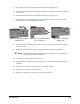
13. Install retainer clip onto male link’s pins. Ensure that the clip’s open end points in the
direction of the motor subassembly (
18HFigure 10-9).
Figure 10-7 Inserting the Master
Link (Male Link)
Figure 10-8 Inserting the Master
Link (Female Link)
Figure 10-9 Installing the
Retainer Clip
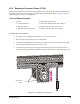
14. Tension the chain by loosening the motor mounting screws allowing the motor’s weight to
remove the slack.
15. Perform a visual inspection of chain to ensure that slack from chain is eliminated.
" NOTE Slack should be eliminated with the motor’s weight (do not push the motor
down to create tension on the chain).
16. Lock motor into position by tightening screws.
17. Perform a function check by revolving the chain 2 to 3 times through its complete range
of motion.
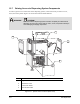
18. Replace any rail-mounted equipment that you removed in Step
19H6.
19. Repeat Steps
20H7-21H15 for the remaining chain.
20. Replace any dispensing system panels you may have removed.