
Instruction Manual


1-4 Introduction
1.5 System Features
The figures in this section show features of the dispensing system. Callouts locate major components,
options, and switches. The item numbers associated with the descriptions correspond to the callout
numbers in the illustration. Detailed operating instructions for some of these features are treated in other
sections of this manual. Unless otherwise noted, Figures 1-1 to 1-8 apply to both the C-740 and C-741
models.
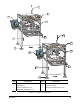
1.5.1 Front View Features
Below are functional descriptions of C-740/C-741 Series Dispensing System components shown in
Figure 1-1.
1. Computer Monitor
The Computer Monitor provides the operator with Easy Coat for Windows XP (ECXP)
software displays.
2. Light Beacon
The Light Beacon is a warning device for the operator. The beacon signals a dispensing status
condition by displaying a colored light and/or issuing an audible tone. Refer to Section 2 - Safety for
additional information.
3. Control Panel
The Control Panel buttons and switches let you control certain programming and run functions. You
can move the Robot (Dispensing Head) and the Conveyor, enable the Safety Interlock, make an
emergency stop, check dispensing status, and adjust valve controls. Refer to Section 6 - Operation
for detailed descriptions of Control Panel functions.
" NOTE The terms Robot and Dispensing Head are synonymous and are used interchangeably
throughout this manual.
4. Dispensing Area
The Dispensing Head, Solvent Cups, Conveyor, Stop Pins, and Board Sensors are all located in the
dispensing area. (See Figure 1-3 and Figure 1-4).
5. Keyboard Tray
The Keyboard and Mouse Tray holds and protects the Computer System keyboard and mouse.
6. Levelers (Foot Pads)
The Levelers are the footpads of the dispensing system. The Levelers are adjusted during installation
and should not need attention unless the system is moved to a new location. To protect the
dispensing system from moving during an earthquake, the Levelers should be anchored to the floor
with bolt anchors. See 2.6 Earthquake Precautions.
7. Lower Front Cabinet
The Lower Front Cabinet allows access to the system Computer, Conveyor Controller Module, and
the Tri-Mode Swirl Box (for the Swirl Coat Module only). See Figure 1-5.