
Instruction Manual

6-18 Operation
6.8.3 Pneumatic Regulators and Gauges
The C-740/C-741 Series Dispensing Systems have the following pneumatic regulators and gauges:
• Main Air Regulator and Gauge
• Conveyor Stop/Clamp Air Regulator and Gauge
• Fluid Pressure Regulator and Gauge
• Air Assist Regulator and Gauge (NOT USED)
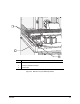
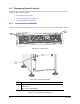
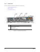
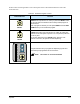
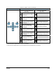
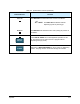
The Main Air and Conveyor Stop/Clamp regulator controls are located at the rear of the system (Figure
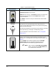
6-7 and Figure 6-8). The Fluid Regulator control is a black knob extending down from the roof of the
dispensing area (Figure 6-9). To reach it you must open the front doors or reach through the light curtain
(if installed) where it is located just behind the front hood.
WARNING! CAUTION!
Make sure the Safety Interlock Recovery Light located on the Control Panel is
ON before you access the inside of the dispensing area. When the light is OFF,
accessing the inside of the dispensing area will cause a non-recoverable
interlock condition to occur. Refer to Section 2 - Safety for additional information.
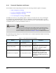
Recommended pressure settings are provided in Table 6-5. See detailed adjustment instructions following
descriptions in this section.
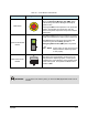
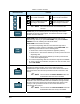
Table 6-5 Recommended Pressure Settings
Device
Recommended
Pressure/Flowrate
Comments
Main Air Pressure Regulator 80 psi (551 kPa)
Facility pressure is 85 to 90 psi (586 to
620 kPa).
Conveyor/Stop Clamp 30 to 40 psi (206 to 275 kPa)
If air pressure is too high, you can
damage parts. If pressure is too low,
the stop pins, board pins, and bar
clamps will not work.
Fluid Air Pressure Regulator 30 to 40 psi (206 to 275 kPa)
Recommended pressure depends on
fluid being dispensed and fluid
applicator being used. Refer to the
Installation and Operations manual
applicable to the Dispensing Valve on
your system.