Century® Series C-740/C-741 Dispensing System Installation, Operations, and Maintenance Manual P/N 7209675, Revision A
NOTICE This is an Asymtek publication which is protected by copyright. Original copyright date 2006. No part of this document may be photocopied, reproduced, or translated to another language without the prior written consent of Asymtek. The information contained in this publication is subject to change without notice. Manuals on the Internet For the convenience of Asymtek customers and field service representatives, copies of Asymtek manuals can be downloaded from: http://www.asymtek.com/support/manuals.
Manual Conventions Bold Text Dispensing system labels, buttons and switches, and software menu selections and commands appear in this text style. Italicized Text Italicized Text refers to a section in this manual or to another document. [Bracketed Text] [Bracketed Text] indicates a single key or key combination to press on a computer keyboard, such as [Enter] or [Alt + Tab]. Text>Text Refers to a series of menu bar commands in Easy Coat for Windows XP (ECXP) software.
TABLE OF CONTENTS 1 2 Introduction.......................................................................................................... 1-1 1.1 Overview .................................................................................................................................. 1-1 1.2 Safety First............................................................................................................................... 1-1 1.3 Getting Started.............................................
4 vi 3.5 Specifications........................................................................................................................... 3-2 3.6 Testing ..................................................................................................................................... 3-2 3.7 Standard Components ............................................................................................................. 3-3 3.7.1 Computer System ............................................
4.10 Electrical Connections ...........................................................................................................4-12 4.11 Exhaust Connection...............................................................................................................4-12 4.12 Connecting Power and Air Supply .........................................................................................4-13 4.13 Earthquake Precautions ..........................................................................
6.9 System Startup/Shutdown .....................................................................................................6-23 6.9.1 Startup .......................................................................................................................6-23 6.9.2 Shutdown...................................................................................................................6-24 6.9.3 Daily Routine Procedures ..........................................................................
.5 Routine Maintenance Procedures ........................................................................................... 9-2 9.5.1 Filling the Fluid Reservoir ............................................................................................ 9-4 9.5.2 Changing Material/Flushing Fluid System ................................................................... 9-5 9.5.3 Emptying the Water Trap............................................................................................. 9-6 9.5.
Appendix B - Electrical Diagrams ............................................................................ B-1 B.1 Overview ..................................................................................................................................B-1 B.2 Safety First...............................................................................................................................B-1 B.3 List of Electrical Diagrams ...................................................................
Table of Figures Figure 1-1 Figure 1-2 Figure 1-3 Figure 1-4 Figure 1-5 Figure 1-6 Figure 1-7 Figure 1-8 C-740/C-741 Front View..................................................................................................... 1-5 C-740/C-741 Control Panel ................................................................................................ 1-7 C-740 Dispensing Area ......................................................................................................
Figure 5-7 Figure 5-8 Figure 5-9 Figure 5-10 Figure 5-11 Figure 5-12 Figure 5-13 Figure 5-14 Figure 5-15 Main Air Regulator and Gauge ........................................................................................... 5-8 Stop/Clamp Air Regulator and Gauge ................................................................................ 5-9 Fluid Pressure Pneumatic Controls ..................................................................................5-10 Robot/Conveyor Position Controls .......
Figure C-1 Figure C-2 Figure C-3 Figure C-4 Figure C-5 Figure C-6 Figure C-7 Figure C-8 Parts List – C-740 Front Open View.................................................................................. C-2 Parts List – C-740 Rear Open View .................................................................................. C-3 Parts List – C-740 Conveyor Components ........................................................................ C-4 Parts List – C-740 Computer Components ..........................
Table of Tables Table 2-1 Table 2-2 Table 2-3 Table 2-4 Laser Fan Width Control Specifications ............................................................................. 2-5 Safety Warning Symbols .................................................................................................... 2-7 Light Beacon Color Indications.........................................................................................2-18 Replaceable Fuse Descriptions.....................................................
1 Introduction 1.1 Overview Congratulations on your choice of the Century C-740/C-741 Series Dispensing System! This manual is intended primarily as a reference for production operators, process engineers, and service technicians. However, others unfamiliar with Asymtek products may also find this manual useful as a general introduction to the system. The Century C-740/C-741 Series Dispensing Systems are designed to meet the diverse needs of the conformal coating market.
1.3 Getting Started 1.3.1 System Status The Century Series Dispensing System is installed and tested on-site by an Asymtek technician. To ensure that the system is in good working order, only Asymtek-trained technicians should install, move, or service the system. 1.3.2 Training In order to optimize the full capabilities and features of your dispensing system, Asymtek recommends certification for all operators, technicians, and engineers using, programming, and servicing the dispensing system.
1.4 Basic System Description All Century C-740/C-741 Series Dispensing Systems have a standard platform. Optional components may be added to suit your particular requirements. Your system was configured for your application at the Asymtek factory prior to shipping. Standard and optional equipment is listed below. Brief descriptions of all features are found later in this section. 1.4.1 Standard Equipment 1.4.
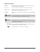
1.5 System Features The figures in this section show features of the dispensing system. Callouts locate major components, options, and switches. The item numbers associated with the descriptions correspond to the callout numbers in the illustration. Detailed operating instructions for some of these features are treated in other sections of this manual. Unless otherwise noted, Figures 1-1 to 1-8 apply to both the C-740 and C-741 models. 1.5.
2 3 1 4 2 5 7 3 C-740 6 4 1 5 7 C-741 6 Item Description Item Description 1 Computer Monitor 5 Keyboard Tray (keyboard and mouse) 2 Light Beacon 6 Leveler (foot pad) 3 Control Panel (Figure 1-2) 7 Lower Front Cabinet (Figure 1-5) 4 Dispensing Area (Figure 1-3) Figure 1-1 C-740/C-741 Front View Introduction 1-5
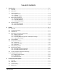
1.5.1.1 Control Panel Below are descriptions of C-740/C-741 Series Dispensing System Control Panel buttons as shown in Figure 1-2. " 1. NOTE Refer to Section 6 - Operation for detailed descriptions of all Control Panel buttons and functions. Start/Stop Buttons The Start and Stop buttons are push buttons located on the Control Panel. They control the power to the dispensing system.
2 3 4 1 5 Item Description 1 Start/Stop Buttons 2 Motion Controls 3 Interlock Keyswitch 4 EMO Button 5 ESD Grounding Strap Connector Figure 1-2 C-740/C-741 Control Panel Introduction 1-7
1.5.1.2 Dispensing Area Below are functional descriptions of C-740/C-741 Series Dispensing System components shown in Figure 1-3. 1. Solvent Cups The Century C-740 conveyorized system has two 125 ml stainless steel cups that are installed on separate brackets mounted to the front Conveyor rail. One cup holds solvent for cleaning the dispensing needle. A second cup is used for the purging of conformal coating fluid.
1 2 3 4 Item Description 1 Solvent Cups 2 Dispensing Head 3 Board Pins 4 Front Doors Figure 1-3 C-740 Dispensing Area Introduction 1-9
1.5.1.3 Dispensing Area Close Up Below are functional descriptions of C-740/C-741 Series Dispensing System components shown in Figure 1-4. 1. Board Sensor (C-740) Mounted on the Conveyor rail within the dispense zone, the Board Sensor detects the presence of a workpiece entering the system. The signal is sent to the Conveyor Controller, which halts Conveyor motion and lowers Stop Pins to hold the part in place for dispensing. 2.
1 3 2 C-740 with Chain Conveyor 4 5 6 C-741 with Adjustable Tooling Rails Item Description C-741 with Tooling Plate Item Description 1 Board Sensor 4 Fluid Dispensing Applicator 2 Chain Conveyor (C-740) 5 Tooling Plate 3 Stop Pin 6 Adjustable Tooling Rails Figure 1-4 C-740/C-741 Dispensing Area Close-up Introduction 1-11
1.5.1.4 Lower Front Cabinet Below are functional descriptions of C-740/C-741 Series Dispensing System components shown in Figure 1-5. 1. Computer The Computer System is used to create and run dispensing programs with the Asymtek Easy Coat for Windows XP (ECXP) dispensing software. 2. Conveyor Controller Module (C-740) The Conveyor Controller module monitors the SMEMA interface and controls the Conveyor indexing operations.
2 1 Item 3 Description 1 Computer 2 Conveyor Controller Module 3 Tri-Mode Swirl Box (Optional) Figure 1-5 C-740 Lower Front Cabinet Introduction 1-13
1.5.2 Rear View Features Below are functional descriptions of C-740/C-741 Series Dispensing System components shown in Figure 1-6. 1. Main Air Regulator The Main Air Regulator controls air pressure supplied to the dispensing system through the Main Air Inlet. 2. Main Air Inlet The Main Air Inlet connects the Century Series Dispensing System to your facility air supply. 3. Main Air Gauge The Main Air Gauge indicates the air pressure to which the Main Air Regulator is set.
1 2 3 4 5 10 6 9 7 8 Item Description Item Description 1 Main Air Regulator 6 Low Fluid Sensor 2 Main Air Inlet 7 Fluid Reservoir (5 gallon) 3 Main Air Gauge 8 Fluid Reservoir (1 gallon) 4 Air Filter and Water Trap 9 Manual Material Change Over Option 5 Exhaust Vent Duct 10 Fluid Filter Figure 1-6 Rear View (with Material Changeover Option) Introduction 1-15
1.5.2.1 Right Rear View (Close-up) Below are functional descriptions of C-740/C-741 Series Dispensing System components shown in Figure 1-7. 1. Stop/Clamp Air Gauge (C-740) The Stop/Clamp Air Gauge indicates the air pressure to which the Stop/Clamp Air Regulator is set. The recommended setting is 206 to 275 kPa (30-40 psi). 2. Stop/Clamp Air Regulator (C-740) The Stop/Clamp Air Regulator controls the air pressure supplied to the Stop Pins and Board Pins on the Conveyor. 3.
1 2 3 Item Description 1 Stop/Clamp Air Gauge 2 Stop/Clamp Air Regulator 3 Reservoir Air Pressure Pneumatic Switch Figure 1-7 Right Rear Close-up Introduction 1-17
1.5.2.2 Lower Rear View Below are functional descriptions of the C-740/C-741 Series Dispensing System components shown in Figure 1-8. 1. Main Power Inlet The Main Power Inlet connects the Main Power Cord from the facility power source to the dispensing system. 2. Main Power Circuit Breaker The Main Power Circuit Breaker controls all electrical power to the entire system including the dispensing system, Computer, and Computer Monitor. 3.
4 3 5 6 2 1 7 8 Item Description 1 Main Power Inlet 2 Main Power Circuit Breaker 3 Power Manager Module 4 Tri-Mode Swirl Box (Optional) 5 Conveyor Controller Module (C-740) 6 Computer 7 SMEMA Connector (upstream) 8 SMEMA Connector (downstream) Figure 1-8 Lower Rear View Introduction 1-19
2 Safety 2.1 Overview This section is intended to provide basic safety information necessary for operating and servicing the Century C-740/C-741 Series Dispensing System.
2.4 Basic Safety Precautions and Practices Compliance with the following recommended precautions and practices will prevent personal injury or damage to property during Century C-740/C-741 Series Dispensing System operation and maintenance. WARNING! CAUTION! Failure to comply with any of the safety recommendations could cause serious injury to the user or damage to the dispensing system. 2.4.
• Where volatile organic compound (VOC) emissions can exceed safe limits, facility ventilation and filtration systems must be operational. • Provide adequate space around the dispensing system to allow for movement of maintenance and service personnel. Allow space for access doors and service panels to open fully. • Make sure all facility power sources are safely grounded. • Routinely inspect all air hoses and electrical cables for damage.
2.4.4 High-Pressure Fluids High-pressure fluids, unless they are safely contained, are extremely hazardous. Always relieve fluid pressure before adjusting or servicing high-pressure equipment. A jet of high-pressure fluid can cut like a knife and cause serious bodily injury, amputation, or death. Fluids penetrating the skin can also cause toxic poisoning. If you suffer a fluid injection injury, seek medical care immediately.
2.5 Laser Radiation The optional Laser Fan Width Control uses a Class II laser sensor. The following safety precautions should be observed in addition to the standard coating system safety precautions. • Operate the Laser Fan Width Control only according to the procedures described in the instructions included. Failure to do so may result in injury due to exposure to the laser beam. • DO NOT look directly at the laser beam.
2.6 2.6.1 Earthquake Precautions Personnel To prevent injury during an earthquake, all personnel should follow facility earthquake safety guidelines. 2.6.2 System Safe Mode Your Century C-740/C-741 Dispensing System is designed to automatically relieve all hazardous electrical, pneumatic, and hydraulic energy in the event that electrical power is lost due to an earthquake. 2.6.
2.7 Safety Warning Labels WARNING! CAUTION! Comply with all safety warning labels or serious injury to personnel or damage to the dispensing system may occur. Worn or damaged labels should be replaced with new labels having the same part number. Warning labels on your Century C-740/C-741 Series Dispensing System point out areas where personnel must use extreme caution to prevent serious injury and property damage.
1 2 Item Description 1 General Warning 2 Electrical Warning Figure 2-2 Safety Warning Labels, Front View 2-8 Safety
1 2 1 1 Item Description 1 Electrical Warning 2 General Warning (on top-side of gauge) Figure 2-3 Safety Warning Labels, Rear View Safety 2-9
2.8 Emergency Shutdown Your Century C-740/C-741 Series Dispensing System features an Emergency Machine Off (EMO) button that the operator or service technician can use to immediately stop all dispensing operations in case of emergency. This feature helps prevent injury to personnel and damage to the dispensing system and workpieces being processed. The EMO button is located on the Control Panel on the front of the dispensing system (Figure 2-4).
2.8.1 Emergency Shutdown Situations As a minimum, activate the EMO in the following situations: WARNING! CAUTION! In an emergency, failure to completely shut down power to the dispensing system with the EMO can cause serious injury to the user and/or damage to the dispensing system. • If anyone is in immediate danger of being injured by moving parts, hazardous materials, or electrical shock. • If valuable dispensing system components or the workpieces are in danger of being damaged.
2.9 Lockout of Electrical and Pneumatic Energy Century C-740/C-741 Series Dispensing System electrical and pneumatic components have been designed in accordance with industry-wide safety standards. However, precautions must still be taken whenever personnel may be exposed to the unexpected power-up and pressurization of the equipment, or release of hazardous electrical or pneumatic energy.
To lock out/tag out pneumatic pressure: 1. Press Stop on the Control Panel. 2. Lock out and tag out AC power as specified earlier in this section. ! When the power is shut off, the Main Air Solenoid Valve shuts off and all hazardous air pressure inside the dispensing system is automatically released. 3. Disconnect the facility air supply hose from the Main Air Inlet and place a warning tag on the Main Air Inlet (Figure 2-6).
2.10 Integrated Safety Systems The C-740/C-741 Series Dispensing Systems have a built-in safety system that automatically protects personnel from being injured by movement of the Dispensing Head and Conveyor. This system consists of the following: • Safety Interlock System • Light Beacon • Electrical Fuses 2.10.1 Safety Interlock System The Safety Interlock System consists of the following: • Safety Interlock Keyswitch • Interlock Door Sensors • Interlock Recovery Light 2.10.1.
CAUTION! Do NOT use the Interlock OFF mode during normal operation. Use OFF mode only when servicing or programming the dispensing system. 2.10.1.1.1 ON Mode When the Interlock is ON (I) and a dispensing program is running, opening the front doors stops all dispensing motion and all position references are lost. This Interlock shutdown condition is indicated by a red System Status Indicator LED on the Control Panel (Figure 2-7) and by a red light on the Light Beacon. For more information, see 2.10.1.
2.10.1.3 Interlock Recovery Light The Interlock Recovery Light (Figure 2-9) is located on the Control Panel and is labeled Interlock Recovery. When the light is ON, you can safely access the inside of the dispensing area. When the light is OFF, accessing the inside of the dispensing area will cause a non-recoverable interlock shutdown to occur. 2 1 Item 3 Description 1 Find Home 2 Interlock Recovery Light 3 System Status Reset Figure 2-9 Interlock Shutdown Recovery 2.10.1.
2.10.2 Light Beacon Located at the top right corner of the system, the Light Beacon is a device that displays system status. The Beacon has four different colored lights that can be constantly ON or flashing and has an audible alarm. The colors on the Light Beacon correspond with the System Status LED’s on the Control Panel. See Table 2-3 for an explanation of each color indication. The Light Beacon can be custom configured to respond to the I/O states of customer equipment. See 4.16 Beacon Configuration.
Table 2-3 Light Beacon Color Indications Beacon Color Dispenser Status ALERT Recovery Procedures • Close doors or remove obstruction, or change INTERLOCK to “0” position. • Press DISPENSER STATUS RESET. • Press FIND HOME. • Select the proper Interlock Mode for your application. 2. System is in an abort state. • Restart the program. 3. INTERLOCK at “I” position, Low Pressure Sensor has been activated. • Check your facility air supply. • Increase ventilation. • Press DISPENSER STATUS RESET.
2.10.3 Electrical Fuses Electrical fuses help prevent injury to personnel and damage to dispensing system electronic components due to overload conditions. Century C-740/C-741 Series Dispensing System fuses are described in Table 2-4. " NOTE See Section 10 - Parts Replacement for fuse replacement instructions. WARNING! CAUTION! Electrical shock and fire can result if fuses are bypassed, incorrectly installed, or a fuse with the wrong rating is used.
3 Component Description 3.1 Overview This section provides a closer look at some of the standard and optional accessories for your Century C-740/C-741 Dispensing System.
3.5 Specifications Refer to Section 11 - Specifications or the applicable technical manual, for performance specifications of the accessories described in this section. 3.6 Testing Functional testing of the component should be performed only by a trained service technician in accordance with the procedures in Section 5 - Power-up and Testing or in the applicable OEM technical manual.
3.7 Standard Components 3.7.1 Computer System The Computer system consists of the Computer, Monitor, Keyboard and Mouse. It runs Easy Coat for Windows XP (ECXP) software. 3.7.2 Easy Coat for Windows XP Software Easy Coat for Windows XP (ECXP) is Asymtek proprietary software for use in a Windows XP environment, developed specifically for Conformal Coating applications. ECXP controls both the Dispensing Head (Robot) movements and the dispensing operation. ECXP features include: 3.7.
When the Keyswitch is in the OFF (0) position, the yellow Beacon light is ON and the Interlock Recovery Light is ON. Opening the Dispensing Area Doors in this state does not disable the dispensing system motion controls. The Interlock Key can be removed to prevent an inadvertent mode change. See 2.10 Integrated Safety Systems for additional information. CAUTION! 3.7.7 Do NOT use the Interlock OFF mode during normal operation. Use the OFF mode only when servicing or programming the dispensing system.
3.8 Optional Equipment Asymtek offers a wide range of options for fine-tuning your dispensing applications. This section introduces options that are currently available for the Century C-740/C-741 Series Dispensing System. 3.8.1 Bar Code Recognition System The Bar Code Recognition System uses a bar code label mounted on the workpiece to select the appropriate coating sequence.
3.8.4 Dual Simultaneous Mounting Bracket The Dual Simultaneous Mounting Bracket, mounted on the Dispensing Head, doubles dispensing capability by accommodating two identical applicators side by side for simultaneous dispensing of a single fluid. The two applicators are controlled independently by ECXP, enabling one coating sequence to coat one or two products at a time. The system is configured for your specific application. Figure 3-2 Dual Simultaneous Mounting Bracket 3.8.
3.8.6 Laser Fan Width Control System Laser Fan Width Control provides closed-loop control of the conformal coating process, automatically compensating for variables within the process environment that can affect fluid fan width. Fan width programming, accomplished through the ECXP software, can be retrofitted to existing Century Series Dispensing Systems equipped with the SC-105 and SC-205 Film Coater Modules.
3.8.7 Flow Monitoring System The Flow Monitoring System monitors the volume of material dispensed. The dispensing system can be programmed to stop, pause, or continue when the dispensed volume falls outside the preset range. In operation, the Computer controller, together with ECXP software, monitors the gear-type Flow Meter when the coating sequence begins. ECXP software records the data in a log file and displays it on the Monitor in bar graph format with time history. Figure 3-4 Flow Meter 3.8.
3.8.10 Inline Inverter Module The Inline Inverter Module provides for a “true” inline process by virtually eliminating manual handling of the workpiece. Automatic one-or two-sided conformal coating reduces board-handling requirements and increases yield. The Inline Inverter Module is SMEMA compatible and features a ventilated and interlocked enclosure. The Inline Inverter Module can be configured for four modes of operation: 1.
3.8.11 Light Curtain The Light Curtain is an optional substitute for transparent front doors. To detect obstructions, the Light Curtain uses an emitter and a receiver. The emitter has a vertical array of infrared lights that shine upon the matching array of light sensors on the receiver. The emitter and receiver are mounted vertically on each side of the dispensing area entrance (see Figure 3-7). When an object 19 mm (0.
The Light Curtain receiver has the following LED operating status indicators: • Green (CLEAR) • Red (BLOCKED) • Yellow (RESET) Table 3-1 describes the meaning of each indicator color. For more information, see the manual included with your Light Curtain. Table 3-1 Light Curtain Status Indicators Indicator Emitter Indicator Color / Behavior Green LED ON Power is ON.
3.8.12 Low Fluid Sensor (for external reservoir) Located within the external reservoir, the Low Fluid Sensor triggers a Light Beacon display and software warning message when the level of coating material is low. The sensor can be set to a level that provides ample time to refill the reservoir before reaching an out-of-material condition. 3.8.13 Low Solvent Cup Sensor The Low Solvent Cup Sensor triggers a Light Beacon display and software warning message when the level of solvent in the cup is low.
3.8.15 Upstream and Downstream SMEMA Sensors Mounted on a bracket attached to the Conveyor rail, upstream and downstream SMEMA sensors allow you to manually load and unload workpieces onto the Conveyor in the absence of upstream or downstream systems. See Figure 3-9.
3.9 Fluid Delivery Systems The Century C-740/C-741 Dispensing System can be configured with any of the Fluid Dispensing Applicators described in Table 3-2.
3.9.2 SC-104HS/SC-105HS High Speed Circulating Film Coater The SC-104HS (4-axis) and SC-105HS (5-axis) apply coatings in a film rather than in an atomized spray produced by conventional airless spray guns. The coaters are fitted with an air-actuated rotating ring mechanism, which rotates the nozzle in 90-degree increments. In addition, the SC-105HS has an airactivated tilt assembly, which allows the stroke to be adjusted from vertical to 30 degrees from vertical.
3.9.3 SC-10XVCS Viscosity Control System The Viscosity Control System maintains consistent temperature of conformal coating fluids. The system includes a fluid dispensing applicator and a heated recirculating fluid circuit to eliminate viscosity changes in temperature-responsive materials. Close-range temperature monitoring keeps the coating process consistent and stable. By controlling the temperature of the conformal coating fluid circuit, viscosity fluctuations can be reduced.
3.9.4 SC-200 Slim Swirl Applicator The Select Coat Slim Swirl Applicator (SC-200) uses Nordson slim swirl 12-hole nozzles to apply materials that do not require heating and therefore do not require circulation. It is air-actuated and the piston and ball travel is micro-adjustable for precise pattern and film-thickness control.
3.9.4.1 Tri-Mode Swirl Box The Tri-Mode Swirl Box is a component of the SC-200 Slim Swirl Applicator. It has two air assist and two fluid regulators and gauges, which regulate the fluid and air-assist pressure to the Fluid Dispensing Applicator. By varying the fluid pressure, conformal coating materials can be dispensed in a bead, monofilament, or swirl pattern. • Bead - A non-atomized stream is applied to areas where: Components are close to keep-out areas. Extra material is required.
3.9.5 SC-204HS/SC-205HS High Speed Non-Circulating Film Coater The SC-204HS (4-axis) and SC-205HS (5-axis) film coaters are used to apply materials that do not require heating and therefore do not require circulation. The coaters are fitted with a rotating ring mechanism, which rotates the nozzle in either a 0-degree or 90-degree position. In addition, the SC-205HS has an air-activated tilt assembly, which allows the stroke to be adjusted from vertical to 30 degrees from vertical.
3.9.6 SC-300 Swirl Coat Applicator The SC-300 Series Swirl Coat Applicator is a non-contact coating applicator providing high-speed delivery and exceptional volumetric control for various fluids, especially “100%-solids” formulations. The SC-300 coats in tight spaces and has unequalled versatility for spray pattern flexibility under program control. The tri-mode operation refers to the combination of fluid and air-assist control. With the air-assist off, the SC-300 dispenses fluid in spots or beads.
4 Installation 4.1 Overview This section describes installation procedures for the Century Series C-740/C-741 Dispensing System and covers the following topics: 4.
4.4 Uncrating and Placing the Dispensing System CAUTION! Check the Tip & Tell and ShockWatch devices, both on the outside of the crate and on the dispensing system, to make sure that the dispensing system has not been dropped or tipped over. If either of these devices has been activated, contact Asymtek Technical Support.
5. Use the 9/16-inch wrench to remove the four (4) bolts that anchor the dispensing system to the floor of the crate. ! There are two anchor brackets on the left side of the dispensing system, and two on the right side. 6. Use the 7/16-inch wrench to remove the eight (8) bolts that hold the four anchor brackets onto the sides of the dispensing system. 7. Use a forklift to gently lift the dispensing system off of the pallet. " NOTE Lift the dispensing system from the bottom, between the feet. 8.
4.5 Unpacking the Dispensing Area CAUTION! If the dispensing system is being installed in a clean room, remove all packaging material and follow facility-recommended procedures before moving components into the clean room. To unpack the dispensing area: 1. Remove all perimeter packaging material from the dispensing area. 2. Remove all tie wraps, tape, foam packaging material, and warning tags from the Dispensing Head and Conveyor (C-740) or Tooling Plate (C-741). " 4.
4.7 Leveling the Dispensing System CAUTION! " NOTE This procedure should only be performed by a trained service technician. If your dispensing system is going to be used as an in-line system, it needs to be leveled and aligned in relation to upstream and downstream systems. This manual does not include alignment procedures for upstream/downstream systems. Alignment procedures should be developed by your facility.
4. Place a level in the center of the left Y-rail of the Conveyor. 5. Observe the position of the bubble within the level’s window. The bubble should be centered, indicating the dispensing system is level from side-to-side. 6. If necessary adjust the Levelers (feet) of the dispensing system as described in Steps 3a and 3b. 7. Place a level in the center of the right Y-rail of the Conveyor. 8. Observe the position of the bubble within the level’s window.
To install the Monitor: 1. Locate the monitor, remove all packaging material, and place the monitor on the swing arm (Figure 4-2A). 2. Attach the monitor to the swing arm with the screws provided (Figure 4-2A). 3. Connect the monitor cable to the monitor extension (Figure 4-2B). 4. Connect one end of the power cable to the monitor and the other to the power cable extension (Figure 4-2B). 5. Locate the monitor power switch and turn it ON (I).
4.8.3 Installing the Keyboard and Mouse CAUTION! Make sure all power sources are disconnected before performing this procedure. This procedure should only be performed by a trained service technician. Tools and Materials Needed: • Keyboard (P/N 194748) • Mouse (P/N 194459) To install the Keyboard and Mouse: 1. Unpack the keyboard from its box and remove all packaging material. 2. Place the keyboard on the keyboard tray so that the left edge of the keyboard lines up with the left edge of the plate.
2 1 Item Description 1 Keyboard 2 Mouse Figure 4-3 Installing the Keyboard and Mouse Installation 4-9
4.8.4 Installing the Light Beacon CAUTION! Make sure all power sources are disconnected before performing this procedure. This procedure should only be performed by a trained service technician. Tools and Materials Needed: • 1/8-inch Hex Key • Light Beacon (P/N LB-C700) To install the Light Beacon: 1. Locate the Light Beacon and remove all packaging material. 2. Locate the beacon cable access port on the top of the dispensing system (Figure 4-4).
1 2 3 4 Item Description 1 Light Beacon 2 Mounting Screws 3 Beacon Cable 4 Access Port Figure 4-4 Installing the Light Beacon Installation 4-11
4.9 Pneumatic Connections The C-740/C-741 Series Dispensing System requires 85 l/min (3 scfm) of clean, dry air delivered through a 12.7 mm (0.5 inch) pipe or hose at 80 to 100 psi (551 to 689 kPa). Connect the air supply to the ¼ -inch NPT quick-disconnect fitting at the Main Air Inlet (Figure 4-5). " NOTE The maximum air supply pressure should not exceed 100 psi (689 kPa). WARNING! CAUTION! All system pneumatic connections should be checked before the main air is connected.
4.12 Connecting Power and Air Supply WARNING! CAUTION! Make sure that your facility meets all requirements listed in Section 11 Specifications. Failure to meet these requirements could result in serious bodily injury to personnel and damage to the dispensing system. CAUTION! This procedure should only be performed by a trained service technician. Tools and Materials Needed: • • Main Power Cable Quick Release Air Hose Nozzle To connect the facilities power and air supply: 1.
5 1 4 2 3 Item Description 1 Exhaust Vent Duct 2 Main Power Circuit Breaker 3 Main Power Inlet 4 Facility Exhaust Ventilation System Ductwork 5 Main Air Inlet Figure 4-5 Connecting the Facilities Power and Air Supply 4-14 Installation
4.13 Earthquake Precautions To prevent the dispensing system from moving during an earthquake, the system should be anchored to the floor. The anchor joint (the point between each screw and the floor) must be able to withstand 100 kg (220 lbs) of pullout force. Each footpad should be anchored to the floor with two screws. Asymtek recommends using M10 x 1.5 (or 3/8–24 UNF) screws. Refer to 2.6 Earthquake Precautions for additional information. 4.14 ECXP Configuration 4.14.1 ECW.
4.15 System Configuration " NOTE If you change your system hardware, use the Reconfigure feature to run the setup procedure again. To reconfigure ECXP: 1. If necessary, install the ECXP software as instructed in the Easy Coat User Guide. ! The installation process is a typical Windows XP installation with user prompts. 2. After the installation is complete, start ECXP by double clicking the ECXP Windows desktop.
3. Select Edit > Edit Mode from the ECXP Operator Screen menu bar to access the ECXP Edit Screen (Figure 4-7). Figure 4-7 ECXP Edit Screen 4. Select Configure > Reconfigure from the ECXP Edit Screen. ! The Configure Dialog Box (Figure 4-8) opens.
5. Select the item to be configured by clicking on it. " NOTE To select more than one item, hold down the CTRL key while selecting additional items. 6. When you are finished, click on OK. ! The software must be restarted in order to perform the configuration. 7. To close the ECXP Edit Screen and return to the Operator Screen, click on File > Exit from the menu bar. 8. To exit ECXP, click on or select or select File > Exit from the Operator Screen menu bar. 9.
4.16 Beacon Configuration The behavior of the Light Beacon can be customized to respond to the I/O states of customer equipment added to the system. Beacon Configuration is only turned on if both Custom System and Configurable Beacon options are chosen during initial system configuration or reconfiguration. A separate beacon.ini file is used to store the beacon configuration settings. The operation of the beacon depends on the machine firmware.
d. Click on the Fault Color field and select a color. ! This is the color of the Fault Message displayed on the Fault Monitor. e. Click on the Trigger Message field and select a trigger for the fault from the dropdown menu, or type in any other message that goes into the fault log. f. Click on the Clear Message field and select the event that clears the message from the dropdown menu, or type in any other message that goes into the fault log. 4. Create a Subsystem. a.
5 5.1 Power-up and Testing Overview Once you have performed all of the procedures described in Section 4 - Installation, you are ready to power-up the dispensing system. This section describes the power-up and testing procedures for making sure that all system components are functioning and communicating properly.
5 1 4 2 3 Item Description 1 Exhaust Vent Duct 2 Main Power Circuit Breaker 3 Main Power Inlet 4 Facility Exhaust Ventilation System Ductwork 5 Main Air Inlet Figure 5-1 Power, Air, and Exhaust Connections 5-2 Power-up and Testing
5. Turn the Computer Power Switch to the ON (I) position. 6. Check the EMO button to see if it has been activated. If it has been activated, deactivate it by turning the red knob clockwise until the knob pops out. 7. Press Start on the Control Panel (Figure 5-2). " NOTE The dispensing system turns on after an approximate 60-second vent air time delay. Verify that the red Vent Air LED on the control panel is blinking. If it is on and not blinking, the exhaust is inadequate.
5.4 Starting Easy Coat for Windows (ECXP) To start/exit ECXP: 1. Double click the ECXP " icon on the Windows desktop. ! As an alternative, you may click on the Windows Start menu and select Programs > ECXP to start the ECXP software. ! The Dispenser will find Home in the Z-Axis, Y-Axis, and X-Axis, respectively. ! The ECXP Operator Screen shown in Figure 5-3 will open. NOTE The Operator Screen will vary slightly if the software is configured for a C-741 Series Dispensing System.
5.5 Testing the System After initial installation and power-up, the system must be tested to ensure that it is working properly. This section includes the procedures for testing the following: Robot/Conveyor I/O Conveyor Panel/Mechanics (C-740) Pneumatics Dispensing System Options Robot (Dispensing Head) Function These procedures should be performed on initial installation and after the machine has been moved or serviced. CAUTION! 5.
" NOTE Menu choices may vary depending upon system configuration. 4. Select Robot Utilities > IO Tool from the Utilities menu. ! A dialog box opens containing a list of Robot inputs and outputs, grouped by tabs (Figure 5-5). 5. Click on the I/O’s to verify that they are working properly. ! Clicking on an input or output should toggle it ON or OFF. ! When you are done, select File > Exit from the menu bar or click on ECXP Operator Screen.
To test the Conveyor I/O (C-740 only): 1. Follow the instructions in 5.4 Starting Easy Coat for Windows (ECXP) to start ECXP. 2. Select Edit > Edit Mode from the ECXP Operator Screen menu bar to access the ECXP Edit Screen. 3. Select Utilities > Conveyor Utilities > IO Tool from the menu bar. ! A dialog box opens containing lists of Conveyor inputs and outputs, grouped by tabs. 4. Click on the I/O’s to verify that they are working properly (Figure 5-6).
5.7 Pneumatics To check the function of the Main Air Regulator and Gauge: 1. Locate Main Air Regulator at the rear of the dispensing system (Figure 5-7). 2. Rotate the Main Air Regulator counterclockwise until the Main Air Gauge registers 0 psi. 3. Rotate it clockwise until the Main Air Gauge registers 85-90 psi (586-620 kPa). ! " NOTE If the Main Air Gauge fails to register pressure, verify that the dispensing system is connected to the facility air source.
To check function of the Stop/Clamp Air Regulator and Gauge: 1. Locate the Stop/Clamp Air Regulator adjustment knob at the rear of the dispensing system (Figure 5-8). 2. Unlock the adjustment knob by pulling it out. 3. Rotate the knob counterclockwise until the Stop/Clamp Air Gauge registers 0 psi. 4. Rotate the knob clockwise until the Stop/Clamp Air Gauge registers 55psi (379 kPa). TIP For accurate pressure adjustment, lower the pressure below the desired level and then increase to the desired pressure.
To check function of the Fluid Pressure Regulator and Gauge: 1. Turn the Reservoir Air Pressure Pneumatic Switch to the ON (l) position (Figure 5-9). 2. Locate the Fluid Pressure Regulator adjustment knob underneath the left side of the front hood. 3. Unlock the knob by pulling it downward. 4. Rotate the Fluid Pressure Regulator adjustment knob counterclockwise until the Fluid Pressure Gauge registers 0 psi. 5. Rotate the knob clockwise until the Fluid Pressure Gauge registers 60 psi (413 kPa).
5.8 Robot (Dispensing Head) Function To check function of the Robot: 1. Verify that the dispensing area front doors are closed and the Interlock Keyswitch is in the ON (I) position. ! The Beacon light should be green. 2. Press Robot Enable on the Control Panel (Figure 5-10). 1 2 3 Item 4 5 Description 1 Z-Axis Position Controls 2 Conveyor Enable Button 3 Y-Axis Position Controls 4 X-Axis Position Controls 5 Robot Enable Button Figure 5-10 Robot/Conveyor Position Controls 3.
8. Press the EMO button on the Control Panel. 9. Verify that power has been cut to the dispensing system by testing the front panel controls. ! If front panel controls are still active, contact Asymtek Technical Support. 10. Turn the EMO button clockwise until it pops back out. 11. Press Start on the Control Panel. 12. Press System Status Reset, Conveyer Status Reset and Find Home on the Control Panel. ! 5.8.1 The Robot should move to the extreme front left corner of the dispensing area.
The Robot Utilities commands are described in Table 5-1. Table 5-1 ECXP Robot Utilities Commands ECXP Command Home Robot Terminal Description Sends the Robot to the XYZ machine origin. Displays a terminal window that is used to send ACL commands to the Robot Controller. The ACL commands are immediately executed. Analog Output Opens a dialog box with an entry field and a slider bar for each analog output in your system.
5.9 Conveyor Panel/Mechanics (C-740) To check function of the Conveyor: 1. Press Convyr Enable on the Control Panel (Figure 5-10). 2. Use the Position Controls on the Conveyor Control Panel to move the Conveyor backward and forward, making sure that the movement is smooth and controlled. ! If you notice any unusual movement such as slipping, stuttering or vibrating, refer to Section 8 - Troubleshooting. 3. Press Conveyor Status Reset on the Control Panel. 4.
Figure 5-13 ECXP Edit Screen - Conveyor Utilities Menu 5.9.1 ECXP Conveyor Utilities In addition to the IO Tool described earlier in this section, the following ECXP commands, shown in Table 5-3, may also be used to test and set up the Conveyor. To access the Utilities menu, click on Edit > Edit Mode from the ECXP Operator Screen. To access the Conveyor Utilities commands, click on Utilities > Conveyor Utilities from the ECXP Edit screen menu bar (Figure 5-13).
5.10 Dispensing System Options Perform the following ECXP commands to make sure that the various dispensing system options are functioning properly. 5.10.1 Laser Fan Width Control If the system is equipped with Laser Fan Width Control, you may use ECXP to test and adjust pressure as follows: 1. Select Edit > Edit Mode from the ECXP Operator Screen to access the ECXP Edit Screen. 2. Select Utilities > Pressure Adjust from the menu bar.
Figure 5-15 Pressure Output Dialog Box 4. Enter a value in the Analog Output field and press the [Tab] key on your keyboard. ! As an alternative, you may use the slider bar in the dialog box to adjust the pressure. It may take several seconds for the pressure to change and a value to appear. 5. Click on the ON button to turn the output on. Click on the OFF button to turn it off. 6. Click and hold on the Pulse button to turn the output on. The output turns off when you release the button. 5.10.
6 Operation 6.1 Overview Before operating your Century C-740/C-741 Dispensing System, it may be helpful to familiarize yourself with the basics of how the system works. This section covers the following topics: " 6.
6.4 Detailed Operation (C-740) During operational setup of the C-740 inline system, the part enters the system using SMEMA (Surface Mount Equipment Manufacturers Association) handshakes. It moves to the dispensing area where the conformal coating is applied and then exits the system. Conformal coating application programs are created using the Easy Coat for Windows XP (ECXP) software installed on the system. 6.4.
Production Run Started Operator enters ECXP Command “Start Production.” Part Enters the System 1. If system dispense part sensor is clear, then system sends SMEMA signal to upstream machine – “Request for Board.” 2. Stop Pin lowers. 3. When upstream machine is ready, it sends SMEMA signal to dispensing system – “Board Ready to Send.” 4. While both SMEMA signals are high, the Conveyor indexes part toward dispensing area. 5. Part Sensor detects part. 6. Conveyor stops. 7.
6.5 Computer System The computer is located inside the lower cabinet. The CD-ROM drive, disk drive, power switch and reset buttons are located on the front of the computer. Access to connections at the rear of the computer should be limited to service technicians. Conformal coating dispensing programs are created using the ECXP software installed in your system. Dispensing programs are stored on the computer hard drive. 6.5.
1 2 3 4 Item Description 1 DVD/CD Drive 2 Power Switch 3 1.44 MB 3.5-inch Disk Drive 4 Reset Button Figure 6-2 Computer Front Panel 6.5.1.2 Computer Operation The computer is usually left ON so that power comes on when the dispensing system is turned ON. However, to clear major software and system failures, you may need to turn OFF or reboot the computer. If possible, save any open files and close all programs before performing the following procedures. To turn the Computer OFF and ON: 1.
To reboot the Computer: 1. To reboot the computer, press the Reset button on the front face of the computer. 2. The computer will turn OFF briefly and then back ON, as indicated by the power indicator. ! Read and act upon any screen prompts. 3. Restart ECXP by double-clicking the ECXP 6.6 icon Dispensing Operations All dispensing operations take place in a workcell. The workcell contains a robot and a fluid dispensing applicator mounted on the robot tool arm. 6.6.1 Robot Concepts 6.6.1.
6.6.2 Coordinate Systems All positioning in the workcell is done with reference to sets of position coordinates, called Reference Frames. As you face the front of the workcell, the X-axis is left to right, the Y-axis is front to rear, and the Z-axis is up and down. Three different sets of Reference Frames are used: Robot Reference Frame, Product Reference Frame and Pattern Reference Frame.
6.7 Conveyor Operations 6.7.1 Chain Conveyor (C-740) The chain conveyor, standard on the Century Series C-740 Dispensing System, transports the workpiece into and out of the dispensing system. Operation of the conveyor is automatic during production runs. An optical sensor detects the part as it arrives, triggering the Conveyor Controller Module to activate the Stop Pin to stop the part at the correct location. Board pins in the dispense zone secure the part in place during fluid dispensing.
1 2 3 Item Description 1 Conveyor Rails 2 Conveyor Adjustment Clamp 3 Hand Crank Figure 6-4 Manual Conveyor Width Adjustment Operation 6-9
6.8 Dispensing System Controls This subsection explains the general operation and use of dispensing system operational controls and indicators. These controls include: 6.8.1 • Power Buttons and Switches • Control Panel Buttons and Indicators • Pneumatic Regulators and Gauges Power Buttons and Switches Primary power buttons and switches are shown in Figure 6-5. Their functions are described in Table 6-1.
Table 6-1 Power Buttons and Switches Button/Switch Appearance Function Located at the right end of the Control Panel, the large, red Emergency Machine OFF (EMO) button cuts electricity to the Power Manager and stops all system motion. EMO Button Pressing the EMO vents all pressure in the pneumatic system, de-energizes the robot motors, and cuts power to all system components except the Computer and Monitor.
6.8.
Refer to Table 6-2 through Table 6-4 for a description of the Control Panel buttons for each of the functional areas. Table 6-2 Download Program Controls Button/Indicator Function ABORT halts a production run. After you press the ABORT button, its red LED lights to indicate that the currently loaded program is discontinued. ABORT V PAUSE After a program is aborted you must press RESET and then FIND HOME before you can restart the program. PAUSE temporarily stops a production run.
Table 6-3 Motion Controls Button/Indicator Z-AXIS Function Moves the Dispensing Head up in small* increments. Moves the Dispensing Head down in small* increments. Moves the Dispensing Head up in large** increments. Moves the Dispensing Head down in large** increments. " TEACH NOTE The Z-Axis arrows are non-functional for the conveyor. TEACH lets you set a desired point on the dispensing surface when prompted by the Easy Coat program. The software stores the “taught” location for future reference.
Table 6-3 Motion Controls (continued) Button/Indicator Function Dispensing Head Response (XY-Axis) Conveyor Response (XY-Axis) Moves the Dispensing Head to the back in small* increments. Moves the Dispensing Head to the front in small* increments. CONVYR ENABLE ROBOT ENABLE Moves the Dispensing Head to the right in small* increments. Moves the Conveyor to the right in small* increments. Moves the Dispensing Head to the left in small* increments. Moves the Conveyor to the left in small* increments.
Table 6-4 System Status Controls Button/Indicator CONVEYOR STATUS V PAUSE RESET INTERLOCK RECOVERY INTERLOCK Function CONVEYOR STATUS has two buttons. PAUSE halts the Conveyor. The PAUSE LED lights up to indicate that the Conveyor has been paused. Press PAUSE again to resume Conveyor movement. Press RESET to clear the Conveyor Controller after a fault condition has occurred.
Table 6-4 System Status Controls (continued) Button/Indicator VENT AIR Function The VENT AIR LED illuminates when vent air is insufficient. " MAIN AIR APPLIC ON/OFF PURGE Operation NOTE The VENT AIR LED flashes while the dispensing system is powering up. The MAIN AIR LED illuminates when main (facility) air pressure is insufficient. Press APPLIC ON/OFF to turn fluid applicator operation on and off. This feature can be used to test run a program without dispensing fluid (dry mode).
6.8.3 Pneumatic Regulators and Gauges The C-740/C-741 Series Dispensing Systems have the following pneumatic regulators and gauges: • Main Air Regulator and Gauge • Conveyor Stop/Clamp Air Regulator and Gauge • Fluid Pressure Regulator and Gauge • Air Assist Regulator and Gauge (NOT USED) The Main Air and Conveyor Stop/Clamp regulator controls are located at the rear of the system (Figure 6-7 and Figure 6-8).
6.8.3.1 Main Air Regulator and Gauge The main air inlet provides regulated air pressure to the dispensing system from your facility air source. You can adjust the main air pressure with the Main Air Regulator. The recommended pressure from the facility air supply to the dispensing system is 85 to 90 psi (586 to 620 kPa). To adjust the main air pressure: 1. Verify that the facility air supply is connected to the main air inlet. 2.
6.8.3.2 Conveyor Stop/Clamp Air Regulator and Gauge Located on the right rear of the dispensing system next to the main air inlet, the Stop/Clamp Air Regulator and Gauge controls air pressure supplied to the stop pins and board pins (chain conveyor) and/or bar clamps. The recommended air pressure is 30 to 40 psi (206 to 275 kPa). " NOTE If air pressure is too high, parts may be damaged. If pressure is too low, the stop pins, board pins and bar clamps will not work.
6.8.3.3 Fluid Pressure Regulator and Gauge The Fluid Pressure Regulator controls the pressure of the fluid reservoir for the SC-205 Non-Circulating Film Coater and the SC-200 Slim Swirl Applicator. For the SC-105HS High Speed Film Coater, this regulator controls the pilot pressure to the pilot operated fluid regulator on the rear of the dispensing system. For more details on how the air is used for fluid pump operation and recommended pressure setting, refer to the manual for your specific fluid pump.
6.8.4 Air Assist Regulator and Gauge The Air Assist Pressure Regulator and Gauge set (Figure 6-10) is NOT USED on the C-740/C-741 Dispensing System.
6.9 System Startup/Shutdown This subsection details basic start-up and shutdown procedures based on different levels of operation. The following procedures are offered as general recommendations and suggestions when starting and/or shutting down your Century C-740/C-741 Series Dispensing System. Your actual start-up and shutdown procedures may vary. WARNING! Only authorized service technicians or process engineers should connect power cables to the power source.
6.9.2 Shutdown 6.9.2.1 Emergency Shutdown In case of an emergency or malfunction, press the EMO button. The EMO is the large red button on the Control Panel. Refer to Section 2 -Safety for important information concerning emergency shutdown. WARNING! 6.9.2.2 Power is still available to the power supply and to the Power Manager after an Emergency Shutdown. To fully remove power to the system, all power cords must be disconnected.
6.9.2.3 Extended shutdown If the system will be shut down for several days, or if your coating material has a short pot life, follow the procedures outlined in the appropriate fluid dispensing applicator manual for cleaning and maintenance of the fluid applicator and nozzle. 6.9.2.4 Service Shutdown To shut down for service: 1. Wait for the dispensing program to complete. 2. Verify that all motion has stopped. 3. Press the Stop (0) button on the Control Panel. 4.
6.9.3 Daily Routine Procedures Table 6-6 contains a brief description and instructions for routine procedures that should be performed on a daily basis before and after operating the dispensing system. Table 6-6 Daily Routine Procedures Procedure Description STARTUP Clean Fluid Filter Check the fluid filter and clean if necessary. Refer to 9.5.4 Cleaning the Fluid Filter. Check Main Air Pressure Ensure that the main air pressure is properly adjusted.
6.10 Conformal Coating Setup Procedures This subsection describes the setup procedure for the C-740/C-741 Series Dispensing Systems. Before operating the dispensing system, read all related component manuals and be familiar with the operating characteristics of each of the system components. A thorough understanding of the system will help you to obtain the desired results. WARNING! Allow only qualified personnel to perform the following tasks.
6.10.3 Performing a System Test Once the coating program has been developed, a system test should be performed. The following is a typical series of steps required to perform a system test. 1. Fill the system with material to test coat a small production run. " 2. Following the instructions in 6.11 Loading a Program and 6.12 Running a Program to start your dispensing program.
6.11 Loading a Program Programs can be loaded from both the ECXP Operator Screen (Figure 6-12) and the ECXP Edit Screen (Figure 6-13). Following are detailed instructions on loading a program from both screens. To load a program from the Operator Screen: 1. If a program is currently running, click on the Stop ! button. Production stops after the currently loaded product is coated. 2. Click on the Change Product button or double-click the Current Product field (Figure 6-12). ! The product map opens.
To load a program from the Edit Screen: 1. Make sure you are in the Product Program View by clicking on View > Product Program from the menu bar. ! There will be a checkmark next to Product Program on the View menu when the Product Program view is activated. ! If it is not activated, click on Product Program to activate it. 2. Click on the Open ! button, or click on File > Open Product Program. The Open dialog box appears (Figure 6-13). 3. Select the file you want to load and click on Open.
6.12 Running a Program Programs can be run from both the ECXP Operator Screen (Figure 6-14 and Figure 6-15) and from the ECXP Edit Screen (Figure 6-16). Following are detailed instructions on running a program from both screens. 6.12.1 Operator Screen To run a program from the Operator Screen (C-740 Conveyorized System): 1. Load the program you want to run as described in 6.11 Loading a Program. 2. Click on the Start button. 3.
To run a program from the Operator Screen (C-741 Batch System): 1. Load the program you want to run as described in 6.11 Loading a Program. 2. Load a new product (board or carrier) into the fixture. 3. Click on the Start button and then on the Run Product button.
6.12.2 Edit Screen To run a program from the Edit Screen: 1. Load the program you want to run as described under 6.11 Loading a Program. ! If you have the C-740 Conveyorized System, a new product (board or carrier) is requested from the upstream machine, loaded into the fixture, and coated. ! If you have the C-741 Batch System, load a new product (board or carrier) into the fixture. 2.
6.13 Production Statistics 6.13.1 Database Utility The ECXP Database Utility lets you export production data to ASCII text tables. The tables can then be imported into database or spreadsheet programs for further analysis. By default, ten days of data are stored in the database. " NOTE Old data is purged when ECXP starts. If the database files become very large, database maintenance can delay ECXP startup.
7 Configuration and Characterization 7.1 Overview Your dispensing system is configured at the Asymtek factory prior to shipping. However, if any components have been changed or moved, it may be necessary to reconfigure them. This section contains the following procedures: • Tool Configuration • Inverter Configuration • Characterization • Robot Configuration • Fan Width Configuration • Bar Code Scanner Configuration • Fixture Configuration • Reconfigure • Conveyor Configuration 7.
7.4 Tool Configuration A tool consists of a Fluid Dispensing Applicator and nozzle. The Tool Configuration dialog box allows you to set the offset for each tool and perform a characterization. 7.4.1 Tool Offset Tool Offset is the X, Y, and Z distance from the lower tooling pin on the Z slide (also called the tool flange, or tool arm) to the tool tip (end of nozzle). See Figure 7-1.
To define Tool Offsets: 1. Select the desired tool from drop-down list on the ECXP Edit Screen. See Figure 7-2. 2. Click on Configure > Tools from the Edit Screen menu bar. ! The Tool Configuration dialog box opens. Figure 7-2 Tool Configuration Dialog Box 3. Enter the appropriate Tool Offsets for the X, Y, and Z fields. ! Since the tool tip is in front of and below the tooling pin, the Y and Z offsets are always negative. Positive X is to the right of the tooling pin, as shown in Figure 7-1.
7.5 " Characterization NOTE A characterization must be performed for each tool and each coating material used or as required to ensure quality and consistent dispensing. Many variables, such as material type, temperature, viscosity, substrate type, robot velocities, and dispenser response times affect the coating process. Characterization improves coating placement accuracy and repeatability. The Characterization Wizard helps you adjust program values to compensate for these variables.
2. Click Clear Positions and then click OK to confirm. ! If you have performed a characterization before, the old test area coordinates are used unless you clear them. 3. Click Next. 4. Click Yes when prompted to teach the substrate height. 5. Teach the substrate height. a. Place a characterization sheet (Figure 7-4) in the workcell. b. Click Teach Z c. Click OK 6. Enter the dispense height.
10. Position the tool tip over the left intersection of the dotted lines and click Next. 11. Position the tool over the right intersection of the dotted lines and click Next. 12. Position the tool tip over the right dotted line and the back line and click Next. ! Remove any teaching devices before continuing. 13. Click Next. ! The Wizard will now apply three stripes of material to the test area (See Figure 7-5).
17. The settings will be displayed for your approval. The only variable you can change is the stripe width. To change any other settings, you will have to rerun the characterization. TIP 7.6 To perform a characterization from the ECXP Edit screen, click on Configure > Tools. The Tool Configuration dialog box opens. Select the tab for the tool you wish characterize, then click the Configure button.
7.7 Fixture Configuration Fixture refers to the location at which products are physically constrained in the workcell. It consists of both position (XYZ) coordinates and a corner constraint (Front Left, Front Right, Back Left, or Back Right). On conveyorized systems, the fixture is typically the combination of a clamp and a stop. On nonconveyorized systems, it is usually a manual fixture. 7.7.
To configure a fixture: " NOTE Before configuring the fixture, you must configure the Tool Offsets. Refer to 7.4 Tool Configuration for detailed instructions. 1. To configure a fixture, click on Configure > Fixtures from the ECXP Edit Screen. ! The Fixture Configuration dialog box shown in Figure 7-7 opens. Figure 7-7 ECXP Fixture Configuration 2. Click on the tab for the fixture you are configuring. ! There will be a separate tab for each fixture configured in ECXP. 3.
5. Install the nozzle used to configure the tool on the Fluid Dispensing Applicator to teach the Z-coordinate. See Figure 7-8 for coordinate location. a. To teach the Z-coordinate, carefully lower the nozzle until it is just touching the surface of the board (Z-coordinate on the Side View) and b. Click on the Teach Z button.
7.8 Conveyor Configuration To configure the conveyor: 1. Click on Configure > Conveyor Settings from the ECXP Edit Screen. " ! NOTE The Conveyor Settings dialog box shown in Figure 7-9 opens. The Conveyor Settings dialog box also contains Inverter configuration settings. See 7.9 Inverter Configuration. 2. Enter the desired property values. ! See Table 7-1 for a description and default value for each property. 3. Click OK when done.
Table 7-1 Conveyor Settings Property Description Default Value Belt Acceleration Rate at which the conveyor belt accelerates. 98.4 in./sec Belt Speed Speed at which the conveyor belt moves. 98.4 in./sec Blind Unload If True, only one attempt is made to unload the board to the downstream machine. If no SMEMA acknowledgement is received, then production continues. If False and no SMEMA acknowledgement is received, an error occurs and production stops.
7.9 " Inverter Configuration NOTE You may configure the Inverter through the Conveyor Configuration dialog box or through the Reconfigure function. The recommended method is through the Conveyor Configuration dialog box. If you use the Reconfigure function, all conveyor settings are reset to the factory defaults. You will then have to restore any customized settings. The following procedure uses the Conveyor Configuration dialog box. The Reconfigure method is detailed in 7.12 Reconfigure.
7.10 Robot Configuration " NOTE The Robot Settings dialog box is only used to set the Safe Z Height. To set the Safe Z Height: 1. Click on Configure > Robot Settings from the ECXP Edit Screen menu bar. ! The Robot Settings dialog box opens. See Figure 7-10. Figure 7-10 Robot Settings Dialog Box 2. Move the robot until the tool tip is above all components on the boards you are coating, and any other component in the workcell with which the tool tip could collide. 3.
7.11 Bar Code Scanner Configuration If your system is equipped with the optional Bar Code Scanner, you will need to perform a Scanner configuration. For additional information, refer to the appropriate Scanner User Manual or contact your Asymtek representative. 7.11.
7. Click on the Comm Port tab. Make sure the Host Port settings are: • Baud Rate: 9600 • Parity: Even • Data Bits: 7 • Stop Bits: 1 • Auxiliary port: Disabled 8. Click on the Protocol tab. 9. Set Selected Protocol to Point-to-Point and check the RTS/CTS box. 10. Enable the Postamble and set it CR and LF. 11. Click on the Output tab. 12. Set the Beeper status to On Noread. Choose Volume Level 5. 13. Click on the Apply button on the bottom of the window. ! The Save window opens. 14.
7.12 Reconfigure If you change system hardware, such as the tool, conveyor, inverter, or scanner you can rerun the ECXP setup procedure with the Reconfigure feature. The changes are written to the ECW.INI file. 1. Click on Configure > Reconfigure. ! The Configure dialog box opens. 2. Select the system hardware you want to reconfigure. " NOTE To select more than one item, hold down the [Ctrl] key while selecting additional items. 3. Click on the OK button. 4. Exit ECXP. 5.
8 Troubleshooting 8.1 Overview If you have difficulty operating your dispensing system, use this section to identify a possible solution to the problem. If you have difficulties not listed in this section, or the suggested solution does not correct the problem, contact Asymtek Technical Support. 8.2 Basic System Troubleshooting Table 8-1 Basic System Troubleshooting Symptom Possible Cause Recovery A. Main Power Cable disconnected Connect the Main Power Cable to an AC power source. B.
Table 8-1 Basic System Troubleshooting (continued) Symptom Possible Cause Recovery 1. Press Dispenser Status Reset. 2. Wait three seconds. 3. Press Find Home. A. System is in abort mode - If motion occurs, restart the dispensing program. - If no motion occurs, call a service technician. No response from Control Panel buttons. 1. Close both doors or clear Light Curtain. B. Interlock activated (doors opened or Light Curtain obstructed during dispensing, low air sensor tripped, etc.) 2.
Table 8-1 Basic System Troubleshooting (continued) Symptom Possible Cause Recovery A. Applicator ON/OFF button is OFF Press Applic ON/OFF button. B. Out of fluid Add fluid to reservoir. C. Nozzle is clogged Remove nozzle, visually verify that it is clogged. See the applicable Fluid Dispensing Applicator manual for cleaning instructions. D. Not enough fluid pressure or no fluid pressure Increase fluid pressure.
9 Maintenance 9.1 Overview Performing the recommended maintenance procedures at the intervals suggested in this section increases system life and ensures high quality dispensing performance for every production run.
9.5 Routine Maintenance Procedures WARNING! CAUTION! Before performing any of the maintenance procedures in this section, perform a service shutdown described in 6.9.2.4 Service Shutdown. " NOTE The following maintenance procedures are for the C-740/C-741 Series Dispensing Systems only. Refer to the appropriate manual for recommended maintenance procedures for your specific Fluid Dispensing Applicator. Routine maintenance procedures and required intervals are listed in Table 9-1.
Table 9-1 Routine Maintenance Procedures (Continued) Procedure Confirm that all items on the Daily Routine Checklist are being performed and recorded. Inspect Conveyor rollers, bearings, and chain for surface damage. Ensure that no foreign material adheres to surfaces. Clean and replace as necessary. Check air cylinders for leakage. Correct as required. Test the vent air switch by removing the vent-sensing air line. With the line removed, the dispensing system should perform an emergency stop.
9.5.1 Filling the Fluid Reservoir CAUTION! Make sure to observe the fluid level indicator. Never let the dispensing system run out of fluid as this may damage the fluid applicator. To fill the Fluid Reservoir: 1. Turn the Reservoir Air Pressure Pneumatic Switch to the OFF (0) position. 2. Relieve residual pressure in the Fluid System by opening the Fluid Pressure Relief Valve on the Fluid Reservoir. 3. Open the lid and check that the reservoir is clean and free from foreign materials.
9.5.2 Changing Material/Flushing Fluid System To change material and flush the Fluid System: 1. If applicable, turn off the heater and allow the fluid to cool for at least fifteen minutes. 2. Reduce fluid air pressure to 7 psi (48 kPa). ! Refer to 6.8.3 Pneumatic Regulators and Gauges for instructions on adjusting fluid pressure. 3. Open and drain the Fluid Applicator. ! Refer to the manual for your specific Fluid Applicator for instructions. 4. Disconnect the siphoning hose from the container. 5.
9.5.3 Emptying the Water Trap Moisture from the outside air can condense in the pneumatic system. The Water Trap collects this condensed moisture. You must empty it monthly or whenever it is full. WARNING! Do not remove the steel bowl guard protecting the Water Trap. The bowl is made of polycarbonate plastic, which could rupture if the inside or outside of the bowl is exposed to chemicals incompatible with polycarbonate. To empty the Water Trap: 1.
9.5.4 Cleaning the Fluid Filter To clean the Fluid Filter: 1. Turn the Reservoir Air Pressure Pneumatic Switch to the OFF (0) position. See Figure 9-3. 2. Relieve residual pressure in the Fluid System by opening the Pressure Relief Valve on the Fluid Reservoir. WARNING! To prevent eye injury or irritation, wear safety goggles while performing this procedure. 3. Unscrew the Fluid Filter cap. The Fluid Filter is located inside the housing. ! 4.
9.5.5 Lubricating the Mechanical Drive Cables Periodic lubrication of the C-740/C-741 mechanical drive cables can prevent premature failure of the cables. For dispensing systems operating in a 24/7 environment, the cables should be lubricated every three months. For systems operating in a single-shift environment, this should be done at six-month intervals. WARNING! Rapid movement of the carriage can damage the X and Y motor drive circuitry.
9.5.6 X-Axis Lubrication Lubricating the X-axis bearings on a quarterly basis will ensure smooth Dispensing Head movement and prolong bearing life. Tools and Materials Needed • Grease Gun, 16 oz. Cartridge (P/N 09-2010-00) • Grease Fitting (P/N 43-1064-30) • Grease, Linear Lube (P/N 48-0019) • Ammonia-based Cleaner • Soft Cloth 9.5.6.1 Loading the Grease Gun To load the grease gun: 1. Pull the grease gun handle back until the locking tabs are visible. 2. Twist the lock into position. 3.
9.5.6.2 Lubricating the X-Axis Bearings To lubricate the X-axis bearings: 1. Move the Dispensing Head to the front of the system, using the motion control arrows on the front Control Panel. 2. Lower the Dispensing Head and turn off the dispensing system. CAUTION! Make sure the Fluid Applicator does not contact the substrate when you lower the Dispensing Head. 3. Open the front doors and locate the access hole on the front of the X-axis bearing housing. See Figure 9-5. 4.
9.5.7 Tensioning the Cables Periodic tensioning of the C-740/C-741 mechanical drive cables can prevent premature failure of the cables. For dispensing systems operating in a 24/7 production environment, tension the mechanical drive cables approximately every six months. For systems operating in a single-shift environment (eight hours a day or less), this should be done once a year.
Tools and Materials Needed • Torque Wrench (P/N 199447) • Allen Wrench 9/64 CAUTION! The Robot will move during the tensioning process. Keep clear of the Robot during the movements. Enter the dispensing area only when prompted to do so. To tension the cables: 1. Perform a system startup as described in 6.9.1 Startup. 2. Depressurize Fluid System by turning off air pressure to Fluid Reservoir. 3. Remove the right side cover of the machine.
Figure 9-7 ECXP Tension Procedure ! The Main pattern has only two instructions in it. When it runs it first calls the Tension Procedure. The Tension Procedure calls the Exercise Cable Procedure as needed. 6. Click OK to run the tensioning procedure and follow the on-screen prompts. 7. When the Tension Procedure is completed, the Main Pattern runs the INI File Write instruction, which writes the key, time, and date to the ECW.ini file.
10 Parts Replacement 10.1 Overview This section includes general information for ordering recommended spares and replacement parts for your Century C-740/C-741 Dispensing System. Part numbers can be found on the exploded parts diagrams in Appendix C.
10.3 Parts Ordering Information 10.3.1 Placing Your Order Customers can order spare parts by contacting Asymtek Customer Service. Your Customer Service Representative can take your order or assist you in setting up an account to purchase spare parts through our Internet Web Store.
10.4 Cleaning and Inspection Always clean the area made visible after a failed part is removed from the dispensing system. Inspect the area for signs of what may have caused the part to fail. This may help prevent future part damage. While removing parts that will be reinstalled, visually inspect them for damage. If found undamaged, retain them for reinstallation. Replace damaged parts and hardware as appropriate. 10.
10.7 Gaining Access to Dispensing System Components In order to gain access to some areas of the dispensing system, it will be necessary to remove covers, doors, and access panels. Figure 10-1 shows the location of these features. 9H WARNING! CAUTION! Make sure that the dispensing system has been completely shut down before attempting to remove any panel. Remove doors, covers, and panels carefully to avoid damaging underlying components.
10.8 Replacing Conveyor Chains (C-740) Checking the condition of the conveyor chains should be part of the routine maintenance schedule for the dispensing system. Worn or broken chains should be replaced immediately. Refer to Appendix C for an illustrated parts list of conveyor components.
5. Locate the master link and use the pliers to remove it as described below: a. Remove the retainer clip (Figure 10-3). 1H b. Remove the female link (Figure 10-4). 12H c. Remove the master link (Figure 10-5). 13H Figure 10-3 Removing the Retainer Clip Figure 10-4 Removing the Female Link Figure 10-5 Removing the Master Link (Male Link) 6. Remove any rail-mounted components that interfere with chain removal/replacement. 7. Remove the old chain by sliding it off the conveyor sprockets.
10. Bring the two ends of the chain one chain-link length apart (Figure 10-7). 15H 11. Insert master link’s male link into both ends of the chain so that pins are pointing outboard (Figure 10-7). 16H 12. Install master link’s female link onto both male link’s pins (Figure 10-8). 17H 13. Install retainer clip onto male link’s pins. Ensure that the clip’s open end points in the direction of the motor subassembly (Figure 10-9).
10.9 Replacing Fuses The number of fuses may vary with the configuration of your system. All fuses are clearly identified. Replacement fuse locations for the Century C-740/C-741 Series Dispensing Systems are shown in Figure 10-10. 2H CAUTION! 10.9.1 Always replace fuses with fuses of identical rating and size. Failure to do so will not protect components from damage and may cause fire. Replacement Fuses Replaceable fuses for the Century C-740/C-741 Series Dispensing Systems are listed in Table 10-1.
1 2 3 Item Description 1 Conveyor Controller Module 2 Main Line Fuse 3 Upstream/Downstream Fuse Figure 10-10 Conveyor Controller Fuse Locations Parts Replacement 10-9
10.9.2 Replacing Main Line Fuses CAUTION! This procedure should only be performed by a trained service technician. Tools and Materials Needed • ESD Grounding Strap • Small Flat Head Screwdriver • Replacement Fuse (see Table 10-1) 24H To replace a main line fuse: 1. Perform a service shutdown as described in 6.9.2.4 Service Shutdown. WARNING! Make sure that all electrical and pneumatic power supplies have been turned off and disconnected as described in 6.9.2.4 Service Shutdown .
1 2 Item Description 1 Main Line Fuse 2 Conveyor Controller Module Figure 10-11 Main Line Fuse Replacement Parts Replacement 10-11
10.9.3 Replacing Panel-Mounted Fuses CAUTION! This procedure should only be performed by a trained service technician. To remove and replace the panel mounted fuses: 1. Perform a service shutdown as described in 6.9.2.4 Service Shutdown. WARNING! Make sure that all electrical and pneumatic power supplies have been turned off and disconnected as described in 6.9.2.4 Service Shutdown. Failure to do so may cause serious injury or death. 2. Determine which fuse needs to be replaced. 3.
4 3 2 1 Item Description 1 Fuse Holder 2 Glass Fuse 3 Socket 4 Conveyor Controller Module Figure 10-12 Panel-Mounted Fuse Replacement Parts Replacement 10-13
10.10 Replacing Control Modules CAUTION! This procedure should only be performed by a trained service technician. Tools and Materials Needed 1/8-Inch Hex Key Removable Thread Locker (P/N 40-0019) Clean Soft Cloth To remove and replace a Control Module: 1. Perform a service shutdown as described 6.9.2.4 Service Shutdown. WARNING! Make sure that all electrical and pneumatic power supplies have been turned off and disconnected as described in 6.9.2.4 Service Shutdown.
9. Apply removable thread locker to the four attachment screws and install using the 1/8-inch hex key. 10. Reconnect all cables, cords, and tubes (as applicable) to the appropriate module receptors. 11. To install a pneumatic tube, simply push the tube end into the port until you feel it lock. 12. Perform a system startup as described in 6.9.1 Startup.
11 Specifications 11.1 Overview Century C-740/C-741 Dispensing System specifications are presented in Tables 11-1 through 11-5. These specifications are intended as a convenient reference for personnel planning system relocation, installation, or operation, and others that may have an interest in system performance characteristics. This section provides specifications for the following: • Facility Requirements 0H • Drive System 1H • Conveyor 2H • • 11.
11.3 Facility Requirements Table 11-1 Facility Requirements Facility Requirements System Footprint 917 x 1041 mm (36 x 41 in.) Compressed Air Dry; 40° F Dew Point 80 to 100 psi (551 to 689 kPa), up to 85 l/min (3 scfm) maximum, depending on configuration 0.28 m3/s @ 25 mm water column (600 scfm @ 1.0 in. water column) Required for moisture-sensitive materials – 80 to 100 psi (551 to 689 kPa), up to 340 l/min (12 scfm) 100/120/220/240 VAC, 50/60 Hz, 10 A <70 dBA 295 kg (650 lbs.
11.6 Dispensing Area Table 11-4 Dispensing Area Specifications Dispensing Area Specifications Dispensing Area* Inline: Batch: Fluid Delivery Method 394 x 458 mm (15.5 x 18 in.) 458 x 458 mm (18 x 18 in.) SC-104HS High Speed Film Coater SC-105HS High Speed Film Coater SC-204HS High Speed Non-Circulating Film Coater SC-205 Non-Circulating Film Coater SC-200 Slim Swirl Applicator SC-300 Swirl Coat Applicator * Dispensing area may be reduced by some options. 11.
Appendix A - Pneumatic Diagrams A.1 Overview This appendix contains block diagrams that describe the Century C-740/C-741 Series Dispensing System pneumatic system. The diagrams may help in understanding dispensing system operation and aid in troubleshooting. The diagrams included in this appendix are described in Table A-1. " A.2 NOTE The drawings included in this appendix are the latest revision in effect at the time of publication.
Appendix B - Electrical Diagrams B.1 Overview This appendix contains diagrams that describe the Century C-740/C-741 Series Dispensing System electrical systems. The diagrams may help in understanding dispensing system operation and aid in troubleshooting. The diagrams included in this appendix are described in Table B-1. " B.2 NOTE The drawings included in this appendix are the latest revision in effect at the time of publication.
Appendix C - Illustrated Parts Lists C.1 Overview This appendix contains exploded view drawings that will aid in ordering replacements parts for the Century C-740/C-741 Series Dispensing System. Parts lists are provided in the illustrations listed in Table C-1. C.2 Safety First Before attempting to replace any parts, please review the precautions in Section 2 - Safety. CAUTION! Only Asymtek-trained service technicians should perform troubleshooting, servicing, and parts replacement.
1 14 2 13 12 3 4 11 5 6 10 9 7 8 Item 1 2 3 4 5 6 7 8 9 10 11 12 13 14 Part No.
1 5 2 4 3 Item Part No. Description 1 40-1224 Regulator, System 2 7204866 Gauge, 0-160 psi 3 CC-201W Controller, C-740 Conveyor 4 62-0533-00 Assy., Power Manager, 10A, Time Delay 5 40-2504 Switch, Low Diff. Press.
1 4 3 2 5 6 8 12 11 Item 9 10 Part No. 7 Description 1 115810 Cup, Single Solvent, 125 ml (Cup Only) 2 199070 Assembly, Single Solvent Cup 3 194950 Assembly, Board Sensor, C-740 4 193720 Sprocket, Drive #25, 14 Tooth 5 198799 Stop Pin Over Board w/o Sensor Bracket 6 06-1037-00 Cable Assembly, 2 Belt Motor 7 07-0716-00 Step Motor, 111 in-oz, 1.
2 3 1 4 6 5 Item Part No.
1 13 14 2 12 3 11 4 5 6 7 10 8 Item 1 2 3 4 5 6 7 8 9 10 11 12 13 14 9 Part No.
1 2 5 4 3 Item Part No. Description 1 40-1224 Regulator, System 2 7204866 Gauge, 0-160 psi 3 194390 Assembly, Swirl Box 4 62-0533-00 Assembly, Power Manager, 10A, Time Delay 5 40-2504 Switch, Low Diff. Press.
1 2 3 4 Item Part No.
1 2 5 3 4 Item Part No.
Appendix D - Dispensing System Electronics D.1 " I/O Communications NOTE The following information will aid in integrating process needs with the dispensing system internal controls. Asymtek assumes no responsibility for customer actions in this regard. This information is provided solely for customer convenience. The Century C-740/C-741 dispensing system uses 8-bit I/Os for normal operation of all system components. This information can be used to add accessories, external devices, or sensors.
D.
D.3 " CC-201-W Conveyor Electronics (C-740 only) NOTE Italic items control valve drivers of the same name on the interconnect PCA located inside the mechanics.
D.4 Auxiliary I/O Connector Pinouts Pin 1 on the connector has a shorter retention tab. Pin 1 of the associated PC mounted mating connector is to the right, when facing the back of the dispensing system. Use Asymtek connectors P/N 55-5185 (2 pin), 55-5906 (3 pin), and 55-5908 (4 pin). Input activation requires 5 mA to be sunk to RETURN. Output transistors are 6 mA capable. Refer to Table 8-2 for bit mapping information.
Table D-3 Connector 60-0255-00 PCA Pin Designation Pin Connection 1 CATA 0 2 CATA 1 3 CATA 2 4 CATA 3 5 CATA 4 6 CATA 5 7 CATA 6 8 CATA 7 9 STOP-K 10 COLA 0 11 COLA 1 12 COLA 2 13 COLA 3 14 COLA 4 15 COLA 5 16 COLA 6 17 COLA 7 18 IG (isolated ground) 19 EMA 0 20 EMA 1 21 EMA 2 22 EMA 3 23 EMA 4 24 EMA 5 25 EMA 6 26 EMA 7 Appendix D – Dispensing System Electronics D-5
D.5 Conveyor Controller Rear Connections (C-740 only) Figure D-1 shows the Conveyor Controller on its side to make it easier to read the connections. The Conveyor Controller stands upright in the bottom of the Century C-740 dispensing system. 16H " NOTE The controller is not customer serviceable. Table D-4 Conveyor Controller Rear Connections Item Feature Description 1 FUSE Fuse holder for 0.
D.6 " Robot NOTE The Robot is not customer serviceable. The Robot is factory calibrated. Do not try to repair or calibrate the Robot. The Robot can perform motion on five different levels: • X-axis • Y-axis • Z-axis • Rotate • Tilt Solenoid valves used to trigger the Fluid Dispensing Applicator are located inside the work area. X, Y, and Z motor and solenoid control cables are supplied with the system. Cables are shielded for insulation from external noise sources.
D.8 Rear Connections All connections to the Century Series C-740 dispensing system are accessible from the rear of the unit and shown in Figure D-2. 17H Table D-5 gives a brief description of each connection.
1 5 2 3 4 7 6 9 8 11 12 13 14 15 10 16 17 18 19 20 21 22 23 29 28 27 26 25 24 Figure D-2 C-740 Rear Connections Appendix D – Dispensing System Electronics D-9
Glossary AC: Alternating Current. Bar Code Recognition System: The Bar Code Recognition System uses a bar code label mounted on the workpiece to select a coating sequence. Bead Mode: Conformal coating applied in a nonatomized stream. Available with the SC-200 Slim Swirl Applicator and Tri-Mode Swirl Box. Curing Process: The second step in the Conformal Coating process. After a coating material has been applied, it must be cured (hardened). Current: The flow of electrons through an electrical circuit.
ESD: Electrostatic Discharge. Exhaust Vent Duct: The Exhaust Vent Duct is connected to the facility exhaust system ductwork and removes fumes from the dispensing system. Fixture: Location at which products are physically constrained in the workcell. Consists of both a position (X, Y, Z) and a corner constraint. Flexible IR/Convection Module: Asymtek's inline forced-convection cure module features a flexible design ideal for mid- to high-volume production. Coating materials are cured using infrared heat.
Low Fluid Sensor: Triggers a Light Beacon display or software error message when the level of coating material is low. Main Air Inlet: The Main Air Inlet connects the Century Series Dispensing System to your facility air supply. Main Power Inlet: The Main Power Inlet connects the Main Power cable from the facility power source to the dispensing system. Maintenance: Planned or unplanned activities intended to keep the dispensing system in good working order.
SC-105HS High Speed Film Coater: Asymtek 5-axis circulating Fluid Applicator, with a 0-360° rotate mechanism plus tilt, that applies conformal coating in a film rather than an atomized spray. Tool Offset: The tool offset is the X, Y, and Z distance from the Robot's lower tooling pin to the tool tip (the end of the nozzle). Robot position is calculated using the coordinates of the tooling pin plus the offset.
Index A Access Panels ............................................................... 10-4 Accessories Crate............................................................ 4-4 Adjustable Tooling Rails ....................................... 1-10, 3-3 Air Assist Pressure Regulator and Gauge ..................... 6-22 Air Filter ....................................................................... 1-14 Air Pressure adjusting conveyor stop/clamp air............................ 6-20 adjusting fluid pressure ....
levelers....................................................................... 1-4 leveling ...................................................................... 4-5 lower front cabinet ............................................ 1-4, 1-12 main air gauge.......................................................... 1-14 main air inlet ............................................................ 1-14 main air regulator..................................................... 1-14 main power circuit breaker ......
exhaust connection................................................... 4-13 fluid delivery system.................................................. 4-6 keyboard and mouse .................................................. 4-8 leveling ...................................................................... 4-5 light beacon.............................................................. 4-10 testing......................................................................... 5-5 Integrated Safety Systems.............
lock out/tag out AC Power....................................... 2-12 lock out/tag out pneumatic pressure......................... 2-13 MSDS ........................................................................ 1-1 warning labels ............................................................ 2-7 warning symbols ........................................................ 2-7 Safety Interlock System .........See Integrated Safety Systems SC-104HS High Speed Film Coater .............................