
Manual

4-2 Operation
Detailed Operation
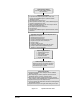
A typical C-730 Flux dispensing process is described below. Setup and programming
procedures are not included in the description. (For information on programming, see the
Fluidmove
®
for Windows NT Installation & User Guide). Figure 4-1 shows a typical
operation flow chart.
1. A part enters the system from an upstream system.
When a part enters the system, a sensor detects its presence, an electrical handshake occurs
between the Asymtek and the upstream machine, and the conveyor indexes the part
according to SMEMA standards.
2. The part stops at the Pre-Dispense Zone.
Stop pins rise to stop the part. The conveyor indexes the part toward the Pre-Dispense stop
pin until the Pre-Dispense Zone sensor detects the part. Then the conveyor belt stops.
3. The part moves to the Dispense Zone.
The stop pins in the Pre-Dispense Zone lower, the stop pins in the Dispense Zone rise, and
the conveyor indexes the part until the Dispense Zone sensor detects the part. Then the belt
stops and the clamp bars rise to hold the part in place during the dispensing process.
Meanwhile, another part loads into the Pre-Dispense Zone. If the system is equipped with
an Under Board Support, the Support will rise with vacuum support pin ON.
4. Dispensing preparations are performed.
> The dispensing head moves to the purge station and the fluid pump purges.
> The fluid is heated as it is dispensed. (The DJ-2200 has a constant, internal fluid-
heating element.
> The vision system turns ON.
> The vision system locates master part fiducials on the part. Fiducials are located as
reference points for the dispensing patterns.
> The height sensor probe is lowered to establish a Z-axis datum. This provides
information for setting the dispense gap in Fluidmove.
5. Fluid is dispensed.
The fluid is dispensed onto the part, according to a pre-programmed dispensing pattern.
See your system’s valve manual for details of your specific dispensing pump.
6. The part exits the system to a downstream system.
When dispensing is complete, the bar clamps release the part, a SMEMA handshake
occurs, and the part moves to the downstream system. Another part is loaded into the
Dispense Zone and clamped in place.