
Manual


2-12 Introduction
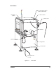
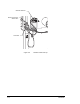
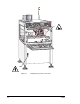
Rear View Features
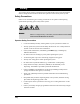
Following are short descriptions of the various features of the dispensing system (shown in
Figure 2-4 and Figure 2-5) and their functions. Detailed operation instructions for some
features are covered in other sections.
Air Filter and Water Trap
The Air Filter and water trap removes particles and impurities in the facility air supply.
Conveyor Air Gauge and Regulator
The Conveyor Air Gauge indicates the air pressure supplied to the bar clamps and stop pins
on the conveyor. The Conveyor Air Regulator is located under the gauge. The
recommended setting is 3.9 kg/cm
2
(55 psi).
External Reservoir
The External Reservoir is available in capacities of 177 cc (6 oz), 591 cc (20 oz), and
3.7 liters (1 gallon). It is recommended only for fluids of low viscosity.
Fluid Filter
The Fluid Filter blocks small particles in the flux fluid from passing to the dispensing
applicator.
Hour Meter (option)
The Hour Meter monitors the dispensing system operation hours for maintenance logging.
Low Air Pressure Sensor (option)
The Low Air Pressure Sensor automatically detects low air pressure to the dispensing
system. During dispensing, when the air pressure goes below a factory preset level, the
sensor activates the interlock safety system, which stops all motion and aborts the
dispensing program. The Light Beacon and the dispenser status LED’s on the control panel
light up. To recover, see Table 6-1.
Main Air Gauge and Regulator
The Main Air Gauge indicates the air pressure supplied to the dispensing system from the
facility air supply. The Main Air Regulator controls the amount of air supplied. The
recommended setting is 551-620 kPa (80-90 psi).
Main Air Inlet
The Main Air Inlet connects the Century Series system to your facility air supply.
Main Power Cable and Inlet
The Main Power Cable and Main Power Inlet connect the Century Series system to the
facility power supply.
Main Power Circuit Breaker
The Main Power Circuit Breaker controls all electrical power to the entire system including
the dispensing system, computer, monitor, and temperature controller.
Nitrogen Inlet
The nitrogen inlet located at the rear of the dispensing system enables connection to your
facility nitrogen supply line.
Service Panel
The Service Panel located in the lower rear of the cabinet protects the system components
inside the cabinet. The Service Panel should not be removed by the operator.
Service Shroud
The Service Shroud protects the rear connectors. Operators should not remove it.