
User guide
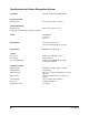

System Specifications 8-3
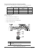
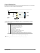
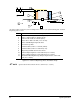
Vision and Dispensing Areas
The following two diagrams show how the vision area and dispensing area intersect for a system with a
single pump and a system with dual-action Dispensing Head.
*Y camera offset used here is just an example. The offset for your system will depend on which
dispensing valve is used.
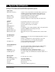
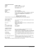
Item Description
1 Rear Conveyor Rail (at extreme rear position)
2 *Y Camera Offset = 0 in. for DispenseJet
3 Vision Area = 506 x 351 mm (20 x 13.8 in)
4 Vision and NO Dispensing in this Area
5 Front Conveyor Rail
6 X Camera Offset = 79 mm (3.1 in)
7 Dispensing Area = 508 x 351 mm (20 x 13.8 in)
8 Dispensing and NO Vision in this Area
9 Working Envelope for Dispensing and Vision: 429 x 351 mm (16.9 x 13.8
in)
Figure 8-1 Vision and Dispensing Areas, Single Pump
?
NOTE Space between rails varies from 25 to 394 mm (1 to 15.5 in).
2
3
4
5
6
9
7
1
8