
User guide


Special Options 13-5
Operation Controls
You can adjust the speed of each fluid valve during dispensing operations. The fluid valve pressure and
fluid syringe pressure are controlled by dispensing system regulators. You can also adjust the toggle
speed for Valve 2 and the spacing between the fluid valves, but the spacing is set at the factory and should
not need to be changed.
Valve 1 and Valve 2 fluid pressure indictors are located on the control panel to the right of the Valve
Speed Control potentiometers (see “Valve Pressure” in the Operation section). When the
Valve Status
indicator light turns ON, the fluid valve is malfunctioning.
Toggle UP/Toggle DOWN and Valve ON/Valve OFF commands are programmed into the dispensing
program using FmNT. For more information on how to insert these commands, contact Asymtek
Technical Support.
Three adjustments must be made to set up a second valve:
• Valve motor speed
• Valve air pressure
• Fluid air pressure
Valve motor speed is controlled by the Valve Speed Control potentiometers labeled
V1 and V2 on the
Control Panel of Century Series systems.
For details on operating the fluid valve for your application, see the installation and operation manual for
the specific valve you are using.
To adjust the fluid valve motor speed:
1. Rotate the Valve Speed Control potentiometer until you have the desired valve flow rate.
2. Reset the locking tab on the control potentiometer.
3. Measure the flow rate.
Adjusting Valve Air Pressure
The DP-3000, DV-6000, and DV-7000 Series pumps use the Valve Pressure Control potentiometers to
control the dispensing process. All other valves use the Fluid Pressure Control potentiometers to control
dispensing. See “Valve Pressure” in the Operation section for the location of the regulators, and
instructions on how to change the settings. For correct pressures and more detailed setup information, see
the installation and operations manual for your specific valve.
Adjusting Fluid Air Pressure
See “Fluid Pressure” in the Operation section for the location of the regulators and instructions on how to
change the settings. For correct pressures, see the installation and operations manual for your specific
valve.
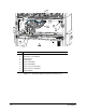
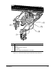
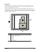
Changing Fluid Valve Spacing
To maximize your dispensing area, the space between Valve 1 and Valve 2 is set up for your application
at the Asymtek factory. Depending on your fluid valves and accessories, you can separate the valves 100
mm (3.72 in) or 87 mm (3.42 in). See Figure 13-3.
For details on this procedure, contact Asymtek Technical Support.