
Instruction Manual

Operation 4-27
Ta
c
tile
H
e
ig
h
t
S
e
n
s
o
r
H
S
-S
e
rie
s
R
T
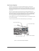
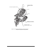
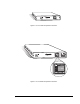
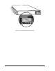
Figure 4-10 Pneumatic and Electrical Connections Shown for
Single-Valve Configuration Using DV-6000
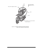
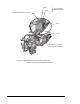
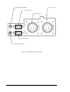
Valve 1 Pressure
Regulator Controls
Black
Blue
Clear (Fluid 1 Regulator Controls)
Valve 1
Valve 2
See Figure 4-11 for correct
electrical power connections
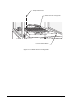
Height Sensor Power
Connectors in Back of Z-Head