
Instruction Manual

Operation 4-9
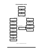
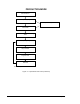
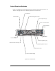
Control Panel and Switches
Figure 4-3 identifies the Control Panel functions, and Power Start and Stop controls. See
Table 4-1 through Table 4-5 for detailed explanations of the functions.
Century
F
lu
id
P
re
s
s
u
re
F
lu
id
2
P
re
s
s
u
re
A NORDSON COMPANY
ZA
xis
Inte
rlock
Inte
rlock
R
eco
very
D
ispenser
Stat u
s
V
1
V
2
Valve
Stat u
s
Valve
P
re
ssure
Valve
2
P
ressure
R
eset
S
E
R
I
E
S
Valve
R
ese
t
F
ind
H
o
m
e
Te
ach
D
ispe
nser
C
o
n
v
e
y
o
r
P
a
u
s
e
C
o
n
v
e
y
o
r
Sta
tu
s
R
e
s
e
t
P
rogram
9
8
7
6
5
4
3
2
1
0
Abort
Sta
r
t
P
a
u
s
e
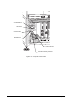
Figure 4-3 Control Panel
START Button
STOP Button
Download Program Controls
Valve 1 Pressure Gauge
Valve 2 Pressure
Gauge
Valve 1 Speed Pot (V1)
EMO Button
Fluid 2
Pressure Gauge
Fluid 1 Pressure Gauge
Directional Controls
Dispensing Status Controls
ESD Ground for Wrist Strap
Valve 2 Speed Pot (V2)