
Instruction Manual

4-2 Operation
Detailed Operation
A typical C-720 dispensing process is described below. Setup and programming procedures
are not included in the description. (For information on programming, see the Fluidmove for
Windows User Guide). Figure 4-1 shows a typical operation flow chart.
1. A part is loaded into the system.
The part is manually placed on the heated vacuum tooling plate.
2. The part is secured on the heated vacuum tooling plate.
Operator activates the vacuum by pressing the yellow ON/OFF button to ON to secure
the work-piece.
3. Dispensing preparations are performed.
" The dispensing head moves to the purge station and the fluid pump purges.
" The fluid can be heated as it is dispensed. (The DV-6000 and DP-3000 may be
equipped with a needle heater.)
" The vision system locates master part fiducials on the part. Fiducials are located as
reference points for the dispensing patterns.
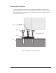
" The height sensor probe is lowered to establish a Z-axis datum. This provides
information for setting the dispense gap in Fluidmove.
4. Fluid is dispensed.
The fluid is dispensed onto the part, according to a pre-programmed dispensing pattern.
See your system’s valve manual for details of your specific dispensing pump.
5. The part is removed from the heated vacuum tooling plate.
When dispensing is complete, the vacuum is deactivated and the part removed. Another
part is loaded into the dispensing system (step 1 above).