
Instruction Manual

2-2 Introduction
Basic System Description
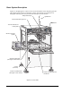
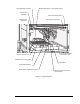
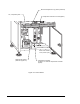
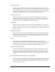
Figure 2-1 through Figure 2-5 show several views and features of the dispensing systems.
The callouts locate all major components, options, and switches seen from that view.
Paragraphs following the views provide brief descriptions of the features.
O
F
F
O
F
F
Century
F
lu
id
P
r
e
s
s
u
r
e
F
lu
id
2
P
r
e
s
s
u
r
e
AN
O
R
D
S
O
N
C
O
M
P
A
N
Y
ZA
x
is
In
te
rlo
ck
In
te
rlo
c
k
R
e
c
o
v
e
ry
D
is
p
e
n
s
e
r
Sta
tus
V
1
V
2
Va
lv
e
Sta
tu
s
Va
lv
e
P
re
s
s
u
re
Va
lve
2
P
re
s
s
u
re
R
e
s
e
t
SERIES
Va
lv
e
R
e
s
e
t
F
in
d
H
o
m
e
Te
a
c
h
D
i
s
p
e
n
s
e
r
Conveyor
P
a
u
s
e
C
o
n
v
e
y
o
r
Sta
t
u
s
R
e
s
e
t
P
r
o
g
r
a
m
9
8
7
6
5
4
3
2
1
0
Abort
Sta
rt
Pause
Figure 2-1 Front View
Control Panel (See Figure 4-1)
Safety Interlock Key
EMO Button
Vacuum Generator for
Tooling Plate
Monitor, Computer
System
Dispensing Work Area
(See Figure 2-3 for Interior)
Leveler
(Foot Pad)
Pullout Tray with Keyboard
and Mouse
Lower Front Cabinet Door
(See Figure 2-3 for Interior)
Light Beacon