
User Manual


vii
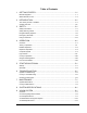
Table of Figures
Figure 2-1 Front View ...........................................................................................................................2-3
Figure 2-2 Dispensing Area (inside dotted line)....................................................................................2-4
Figure 2-3 Lower Cabinet......................................................................................................................2-5
Figure 2-4 Rear View ............................................................................................................................2-9
Figure 2-5 Rear View Close-up ...........................................................................................................2-10
Figure 3-1 Safety Warning Labels, Front View.....................................................................................3-4
Figure 3-2 Safety Warning Labels, Rear View......................................................................................3-5
Figure 3-3 EMO Location on Dispenser Control Panel.........................................................................3-9
Figure 3-4 Main Power Inlet and Main Power Circuit Breaker...........................................................3-10
Figure 3-5 Earthquake Protection, Side View .....................................................................................3-12
Figure 4-1 Operational Flow Chart........................................................................................................4-3
Figure 4-2 Computer Front Panel ..........................................................................................................4-5
Figure 4-3 Control Panel .......................................................................................................................4-8
Figure 4-4 Light Beacon......................................................................................................................4-15
Figure 4-5 Light Curtain......................................................................................................................4-17
Figure 4-6 Light Curtain Receiver LED’s ...........................................................................................4-18
Figure 4-7 Conveyor Zones, Left-to-Right Flow (typical) ..................................................................4-20
Figure 4-8 Conveyor, Front Rail Main Features..................................................................................4-21
Figure 4-9 Main Air and Conveyor Air Gauges and Regulators .........................................................4-25
Figure 4-10 Fluid and Valve Pneumatic Fittings (Connections shown for DJ-2000)............................4-27
Figure 4-11 Fluid Pressure Gauge and Regulator..................................................................................4-28
Figure 4-12 Valve Pressure Gauge and Regulator.................................................................................4-29
Figure 4-13 Conveyor Air Gauge and Regulator...................................................................................4-31
Figure 7-1 Water Trap ...........................................................................................................................7-3
Figure 7-2 Purge Boot Close-up ............................................................................................................7-5
Figure 7-3 Part Sensor Close-up............................................................................................................7-7
Figure 8-1 Dispensing and Vision Areas (Single Pump) .......................................................................8-3
Figure 8-2 Dispensing and Vision Areas (Dual-Action Pumps)............................................................8-3
Figure 9-1 AV-700 Vision System ........................................................................................................9-3
Figure 9-2 F-stop Ring...........................................................................................................................9-5
Figure 9-3 Focus Height Ranges ...........................................................................................................9-9
Figure 9-4 AV-2550 Vision System ....................................................................................................9-10
Figure 10-1 Height Sensor.....................................................................................................................10-1
Figure 10-2 Height Sensor Installation ..................................................................................................10-3
Figure 10-3 Height Sensor Installation with Bracket Spacer.................................................................10-4
Figure 10-4 Probe-to-Needle Alignment ...............................................................................................10-9
Figure 11-1 NSZ Series Needle Sensor .................................................................................................11-1
Figure 11-2 NS Series Needle Sensor....................................................................................................11-2
Figure 12-1 HT-04.................................................................................................................................12-2
Figure 12-2 HT-06.................................................................................................................................12-3
Figure 12-3 HT-10N..............................................................................................................................12-3
Figure 12-4 HT-1000 Temperature Controller or HT-1200-RTD .........................................................12-4
Figure 12-5 HT-2000 Temperature Controller ......................................................................................12-4
Figure 12-6 4-Channel Encap Temperature Controller .........................................................................12-5
Figure 12-7 Needle Heater Connections (not to scale) ..........................................................................12-7
Figure 12-8 HT-06 on a DV-6000 Pump with Luer Lock Fitting..........................................................12-9
Figure 12-9 HT-10N on a DV-6000 Pump ............................................................................................12-9
Figure 13-1 Dual-Action Dispensing Head (Century)...........................................................................13-2
Figure 13-2 Dual-Action Dispensing Head (Millennium).....................................................................13-3
Figure 13-3 DA-700 with Fluid Pumps Detached .................................................................................13-4
Figure 14-1 Top View, Cover Removed; Expanded I/O Connectors ....................................................14-1
Figure 14-2 Low Air Pressure Sensor....................................................................................................14-5
Figure 14-3 Hour Meter.........................................................................................................................14-7
Figure 15-1 XYZ Axes ..........................................................................................................................15-1