
User Manual

Operation 4-5
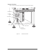
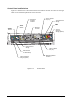
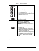
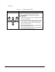
Computer Front Panel
Figure 4-2 shows the front panel control locations of a typical system computer.
H
T
-1
20
0
N
E
E
D
L
E
H
E
A
T
ER
IN
DE
X
A
U
T
O
TU
N
E
SPI
AL
SP2
F
C
O
M
E
G
A
C
N
7
6
0
0
0
EN
T
ER
AN
O
R
D
S
O
N
C
O
M
P
A
N
Y
Figure 4-2 Computer Front Panel
Hard Drive
A
ctivity Indicator
Power Indicator
Power Switch
Rese
t
Floppy Dis
k
Driv
e
CD-ROM Drive