The CD part number for this manual is 78-0027-002, Revision B. The Hardcopy part number is 78-0027-00, Revision B. The Cleanroom part number is 78-0027-00K, Revision B. To reorder this manual, please contact Asymtek, 1-760-431-1919.
Century Series Automated Fluid Dispensing Systems Model C-718SMT Operations Manual P/N 76-0032-00, Revision A 06/2000
NOTICE All information contained in or disclosed by this document is considered proprietary by Asymtek®. By accepting this material the recipient agrees that this material and the information contained therein are held in confidence and in trust and will not be used, reproduced in whole or in part, nor its contents revealed to others, except to meet the purpose for which it was delivered.
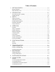
Manual Conventions Labels Dispensing system buttons, labels, switches or connections appear in this text style. Buttons Fluidmove for Windows (FMW) buttons and dialog boxes appear in this text style. Menu Selections All menu selections within FmNT appear in this text style. FILENAME.FM2 Filenames appear in THIS TEXT STYLE. Typed commands, names and values appear in this text style. Level 1 Safety Warning.
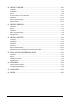
Table of Contents 1 GETTING STARTED...................................................................................1-1 Manuals Supplied.................................................................................................................. 1-1 Which Manuals to Use .......................................................................................................... 1-2 2 INTRODUCTION.........................................................................................
10 HEIGHT SENSOR.....................................................................................10-1 Overview ............................................................................................................................. 10-1 Installation ........................................................................................................................... 10-2 Setup.......................................................................................................................
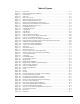
Table of Figures Figure 2-1 Figure 2-2 Figure 2-3 Figure 2-4 Figure 2-5 Figure 3-1 Figure 3-2 Figure 3-3 Figure 3-4 Figure 3-5 Figure 4-1 Figure 4-2 Figure 4-3 Figure 4-4 Figure 4-5 Figure 4-6 Figure 4-7 Figure 4-8 Figure 4-9 Figure 4-10 Figure 4-11 Figure 4-12 Figure 4-13 Figure 7-1 Figure 7-2 Figure 7-3 Figure 8-1 Figure 8-2 Figure 9-1 Figure 9-2 Figure 9-3 Figure 9-4 Figure 10-1 Figure 10-2 Figure 10-3 Figure 10-4 Figure 11-1 Figure 11-2 Figure 12-1 Figure 12-2 Figure 12-3 Figure 12-4 Figure 12-5 Figure
Table of Tables Table 3-1 Table 4-1 Table 4-2 Table 4-3 Table 4-4 Table 4-5 Table 4-6 Table 4-7 Table 4-8 Table 4-9 Table 6-1 Table 6-2 Table 7-1 Table 7-2 Table 7-3 Table 9-1 Table 9-2 Table 9-3 Table 9-4 Table 10-1 Table 11-1 Table 12-1 Table 14-1 Table 14-2 viii Safety Warning Labels............................................................................................................. 3-3 EMO Button...................................................................................................
1 Getting Started Congratulations on your choice of an Asymtek Century® Series Automated Fluid Dispensing System! This section describes the materials that arrive with your system and helps you use the documentation. Manuals Supplied Your Century Series dispensing system arrives with manuals for installation and operation of major system components and software. For some system components, you may receive Original Equipment Manufacturer (OEM) manuals.
Which Manuals to Use The following guide describes when to use each manual. Component Installation or Upgrading To install, reinstall, or upgrade components of your system, see the Century Series Installation & Service Manual. After Installation After Asymtek Technical Support installs your system, see the Century Series Operations Manual (this manual) for operator information such as the system description, option descriptions, safety, startup/shutdown, troubleshooting, and operator level maintenance.
2 Introduction The Century Series C-718SMT Century Series dispensing systems are designed for a wide range of industrial and electronic applications. The C-718SMT dispensing system is designed primarily for Surface Mount Technology (SMT) applications. The system has an in-line conveyor that is SMEMAcompatible and is targeted for dispensing Surface Mount Adhesive (SMA) in mid-range lines.
System Overview Figure 2-1 through Figure 2-5 shows several views and features of the dispensing systems. The callouts locate all major components, options, and switches seen from that view. Paragraphs following the views provide brief descriptions of the features.
Front Views C-718SMT Front View Light Beacon Monitor Control Panel Fluid Pressure Gauge Valve Pressure Gauge START Button EMO Valve 2 Pressure Valve Pressure Fluid 2 Pressure Fluid Pressure Abort STOP Button Pause 9 8 7 6 5 4 Program 3 2 1 Start 0 Z Axis Teach Conveyor Status Conveyor Dispenser Pause Find Home Interlock Recovery Dispenser V1 Status Reset Valve Status Interlock Reset Valve Reset V2 Century S E R I E S 5 15 Grounding Strap Connector 10 A NORDSON COMPANY Va
Dispensing Area Fluid Pump (DJ-2000 shown) Syringe Vision System Valve Pressure Regulator 5 15 Fluid Pressure Regulator 10 Dispensing Head Interior Light (underneath) Dispensing Area Vacuum Support Pin Interlock Door Sensors* Conveyor Under Board Support Under Board Support Switch Height Sensor Purge Station *Doors not shown Figure 2-2 2-4 Dispensing Area (inside dotted line) Introduction
OMEGA CN76000 AUTOTUNE SPI AL SP2 F C HT-1200 NEEDLE HEATER INDEX ENTER Lower Cabinet A NORDSON COMPANY Temperature Controller (HT-1200-RTD, HT-1000, or HT-2000) Computer Conveyor Controller (201W) Figure 2-3 Introduction Lower Cabinet 2-5
Front View Features Following are short descriptions of the various parts and modules of the C-718SMT system (Figure 2-1, Figure 2-2 and Figure 2-3). Detailed operation instructions for some features are covered in other sections. Computer System (computer, monitor, keyboard, mouse) The Computer System is used to create and run dispensing programs with the Asymtek dispensing software Fluidmove® for Windows NT (FmNT). Control Panel The Control Panel mainly uses membrane buttons.
Front Doors The front doors (shown but not called out) have an electrostatic, dissipative surface that does not hold an electrostatic charge. Door sensors connect the front doors to the Safety Interlock system. Grounding Strap Connector The operator’s grounding strap plugs into this connection to prevent Electrostatic Discharge (ESD). Height Sensor (option) The Height Sensor is installed on the dispensing head next to the fluid pump and is controlled by Fluidmove.
Power ON and OFF The Start and Stop buttons are located on the Control Panel and control the power to the dispensing system. Both buttons connect to the Main Power Circuit Breaker at the rear of the system. They are momentary press down buttons. The Start button glows green when pushed, remaining lit until the Stop button or EMO is pressed. When the Stop button is pressed, dispensing activity shuts down.
Rear Views Hour Meter Service Shroud Low Air Pressure Sensor (under shroud) Fan Main Air Inlet Main Power Circuit Breaker Main Power Cable and Inlet Service Panel Figure 2-4 Introduction Rear View 2-9
Air Filter & Water Trap Light Curtain Control Module (Under Cover) Conveyor Air Gauge and Regulator Main Air Gauge and Regulator (T-Bar) Figure 2-5 2-10 High Air Pressure Relief Valve Rear View Close-up Introduction
Rear View Features Following are short descriptions of the various features of the dispensing system (shown in Figure 2-4 and Figure 2-5) and their functions. Detailed operation instructions for some features are covered in other sections. Air Filter and Water Trap The Air Filter and water trap removes particles and impurities in the facility air supply. Conveyor Air Gauge and Regulator The Conveyor Air Gauge indicates the air pressure supplied to the bar clamps and stop pins on the conveyor.
Main Air Gauge and Regulator The Main Air Gauge indicates the air pressure supplied to the dispensing system from the facility air supply. The Main Air Regulator (T-bar) controls the amount of air supplied. The recommended setting is 551-620 kPa (80-90 psi). Main Air Inlet The Main Air Inlet connects the Century Series system to your facility air supply. Main Power Cable and Inlet The Main Power Cable and Main Power Inlet connect the Century Series system to the facility power supply.
3 Safety Your Century Series system is designed to be safe and reliable. This section describes the features and precautions needed to ensure safe operation of the Century Series system. Safety Precautions WARNING! Failure to comply with any of the safety recommendations below could cause serious bodily harm to the user. Please review the following list of safety precautions for the operator and dispensing system before operating your Century Series system.
System Protection Precautions 3-2 • Always wear a grounding strap and connect it to the ESD ground when operating the system. • Be especially careful when dispensing fluids that are caustic or conductive. Wear gloves, and immediately clean up and contain all spills. If fluid gets into internal portions of the dispensing systems, call Asymtek Technical Support immediately. • Maintain a clean and orderly work area. • Follow all recommended system maintenance.
Safety Warning Labels WARNING! CAUTION! Follow all safety warning labels. Failure to comply could cause serious bodily harm to the user and serious damage to the dispensing system. To ensure the safety of all personnel, always observe standard safety precautions and practices. Before using your dispensing system, take a moment to familiarize yourself with the system safety features and warning labels. Table 3-1 shows the four types of warning labels on the dispensing system.
Valve 2 Pressure Valve Pressure Fluid 2 Pressure Fluid Pressure Abort Pause 9 8 7 6 5 4 Program 3 2 1 Start 0 Z Axis Teach Conveyor Status Conveyor Pause Find Home Interlock Recovery Dispenser V1 Status Dispenser Reset Valve Status Interlock Reset Valve Reset V2 Century S E R I E S 3-4 5 15 Figure 3-1 10 A NORDSON COMPANY Safety Warning Labels, Front View Safety
1A 250V J-Type Thermocouple 8A 125V AC OUTPUT 1A 250V 24V Max .
Integrated Safety Systems Your Century Series system offers the safety features described below. Safety Interlock System INTERLOCK is a key-activated safety device located on the Control Panel (see Figure 2-1, Table 4-5: Dispensing Status Control Functions and Table 4-6: Panel / Beacon Colors, Dispensing Status and Recovery Procedures). It is designed to restrict access to the inside of the dispensing system, based on user classification. The Safety Interlock has two modes— ON or OFF.
Light Beacon Located at the top right corner of the system, the Light Beacon is a visual warning device that indicates different Interlock status conditions by turning on a different colored light for each condition. See Table 4-6 for an explanation of each color condition. The colors displayed on the Light Beacon match the colors displayed on the DISPENSER STATUS LED’s on the Control Panel of the Century Series System.
Emergency Shutdown WARNING! Failure to shut down total power to the Century Series system in an emergency with EMO and the Main Power Circuit Breaker could cause serious bodily harm to the user and/or serious damage to the dispensing system. In case of an emergency or malfunction, push EMO (Figure 2-1). EMO cuts power to system components and the temperature controller. All system components connect to the EMO outlet except the computer and monitor.
To shut down in an emergency: 1. Press EMO.
Electrical Power Electrical Power is supplied to the dispensing system through the Main Power Inlet. The Main Power Cable connects the facility AC power source to the Main Power Inlet located on the rear of the Century Series system (Figure 3-4). All personnel working on or around the Century Series system must be aware of all electrical power supply sources. WARNING! When performing service or maintenance work on the system, be sure to lock out power (see “Locking Out Power” on page 3-11).
Locking Out Power WARNING! When performing service or maintenance work on the system, be sure to lockout the power by following the procedure below. Failure to do so could cause serious bodily harm to the user and/or serious damage to the dispensing system. To lockout the Century Series system: 1. Turn OFF (O) the Main Power Circuit Breaker. 2. Unplug the Main Power Cable from the facility source. 3. Lock Main Power cable in a locked box for safety.
Earthquake Precautions To protect the dispensing system from moving during an earthquake, the system must be anchored to the floor. The anchor joint (the point between each screw and the floor) must be able to withstand at least 100 kg (220 lbs.) of pullout force. Each leveler should be anchored to the floor with two screws.
Lifting Precautions WARNING! CAUTION! Failure to follow the Installation or Service Manual procedures for lifting the dispensing system could cause serious bodily harm to the user and/or serious damage to the dispensing system. If you need to move a Century Series system, call a service technician. Refer the service technician to the Century Series Installation Manual or the Century Series Service Manual for instructions on moving the system.
4 Operation ? NOTE Section 3 – Safety must be read along with this section before operating the system. Overview The C-718SMT is an in-line, conveyorized dispensing system that supports mid-range SMT lines. Typically, dispensing processes involve each of the critical operations listed below. The way in which each is accomplished may vary, depending upon system configuration. Theory of Operation In this theory of operation, all configurations are considered and included.
Detailed Operation A typical C-718SMT dispensing process is described below. Setup and programming procedures are not included in the description. (For information on programming, see the Fluidmove® for Windows NT Installation & User Guide). Figure 4-1 shows a typical operation flow chart. 1. A part enters the system from an upstream system.
Production Run Started Operator enters FMW Command-"Run Production" Part Enters the System 1. If Asymtek's Pre-Dispense part sensor is clear, then Asymtek sends SMEMA signal to upstream machine-"Request for Board" 2. Pre-Dispense Zone stop pins rise 3. When upstream machine is ready, it sends SMEMA signal to Asymtek--"Board Ready to Send" 4. While both SMEMA signals are high, the conveyor indexes part toward Pre-Dispense Zone 5. Pre-Dispense part sensor detects part 6. Conveyor stops 7.
Dispenser Operation There are several operation controls and indicators for the dispensing system components. This section explains the general operational use of these controls. Computer System The computer is located inside the lower cabinet. The CD-ROM drive, disk drive, power switch and reset button are located on the front of the computer. Access to connections in the rear of the computer should be limited to service technicians. The computer runs Fluidmove® for Windows NT (FmNT).
Computer Front Panel Figure 4-2 shows the front panel control locations of a typical system computer.
CD-ROM Drive Press the button below and to the right of the disk tray to insert or eject a disk. Floppy Disk Drive The computer has at least one 3.5-inch, 1.4MB floppy disk drive. Insert disks through the drive door flap. Press the small button on the lower right to eject a disk. Hard Disk Drive Internal hard drive. Hard Drive Activity Indicator This light blinks when the hard drive is active. Power Indicator The Power Indicator is green when power to the computer is ON.
Computer Operation The computer is usually left ON so that power comes on when the dispensing system is turned ON. However, to clear major software and system failures, you may need to separately turn ON or OFF and reboot the computer. Follow the procedures below. To turn OFF or reboot the computer while the dispensing system is ON: 1. If possible, save any open files and close all programs. > If the computer is completely locked-up and unresponsive, skip to Step 2.
Control Panel and Switches Figure 4-3 identifies the Control Panel functions and Power Switch. See Table 4-1 through Table 4-5 for detailed explanations of the functions.
EMO (Emergency Machine OFF) Table 4-1 Button EMO Button Function Located at the right end of the Control Panel, the large, red EMO (Emergency Machine OFF) button cuts electricity to the power manager and stops all system motion. EMO cuts power to all system components except the computer and the monitor. Switches WARNING! To cut power to the entire system, you must turn OFF (O) the main power, computer, and monitor.
Control Panel The Control Panel is divided into three functional areas: • Download Program Controls • Motion Controls • Dispensing Status/Safety Interlock Controls The following tables describe each Control Panel function. Table 4-3 Button/Indicator ABORT PAUSE Download Program Control Functions Function ABORT halts a production run. After you press the ABORT button, its red LED lights to indicate that the currently loaded program is discontinued.
Table 4-4 Button/Indicator Motion Control Functions Function Z AXIS Z-Axis Controls (up/down) • Click and release a single arrow to move dispensing head 1 mm (0.001 inches) • Click and hold single arrow to move dispensing head 25.4 mm per second (1 in/sec) • Click and hold double arrow to move dispensing head 50-75 mm per second (2-3 in/sec) TEACH TEACH lets you set a desired point on the dispensing surface with the Fluidmove program. The location of the fiducial is stored by the software.
(Continued) Table 4-4 Button/Indicator Motion Control Functions Function X/Y-Axis Controls (left/right, front/rear) and Conveyor Controls (conveyor belt, board clamp mechanism Press DISPENSER to control the X/Y motion of the dispensing head: CONVEYOR 4-12 DISPENSER • The left and right arrows move the dispensing head to the left or right (X-Axis) • The up and down arrows move the dispensing head to the rear and front of the dispensing area (Y-Axis) • Click and release a single arrow to move dispe
Table 4-5 Button/Indicator CONVEYOR STATUS Program Paused PAUSE Fault Condition RESET Dispensing Status Control Functions Function CONVEYOR STATUS has two buttons. PAUSE halts the conveyor, and its LED indicates that the Conveyor has been paused. Press PAUSE to resume conveyor movement. Press RESET to clear the controller after a fault condition has occurred.
Table 4-5 Button/Indicator V1 VALVE STATUS V2 Dispensing Status Control Functions (Continued) Function VALVE STATUS LED turns ON if there is a problem with the fluid pump motor. It usually indicates that the pump electronics (overcurrent protection circuitry) has detected a surge of power. When the LED is ON, the valve is disabled. V1 is Valve 1. V2 is Valve 2. To recover, press VALVE RESET. If the problem persists, the pump may need to be cleaned.
Light Beacon Light Beacon Valve 2 Pre Valve Pressure Conveyor Status Conveyor Interlock Recovery Dispenser V1 Status Dispenser Pause Valve Status Interlock Reset Reset Valve Reset V2 Century S Figure 4-4 E R I E S Light Beacon The Light Beacon is ON whenever the dispensing system is ON. The Beacon indicates the dispenser’s status by displaying a red, yellow, green or blue light. The meaning of each color is described in Table 4-6.
Table 4-6 Panel / Beacon Color RED Panel / Beacon Colors, Dispensing Status and Recovery Procedures Dispensing Status Recovery Procedures ALERT All motion, outputs, valve and motion controls are disabled. One of the following conditions exists: A. Doors open or light curtain is obstructed when system is moving, INTERLOCK at I. B. System is in an abort state. A or B: 1. Close doors or remove obstruction, or change INTERLOCK to O. 2. Press DISPENSER STATUS RESET. 3. Press FIND HOME. 4.
Light Curtain The Light Curtain is an optional substitute for transparent front doors, and it operates according to the same rules. To detect obstructions the Curtain uses an emitter and a receiver. The emitter has a vertical array of infrared lights which shine upon the receiver’s matching array of light sensors (Figure 4-5). The emitter and receiver are mounted vertically on either side of the dispenser’s front entrance. When an object 19mm (0.
Green LED Red LED Yellow LED Figure 4-6 Table 4-7 Light Curtain Receiver LED’s Light Curtain Receiver Status Indicators Indicator Green Red Yellow On steadily CLEAR BLOCKED RESET Flashing BLANKING LOCKOUT ALIGNMENT The Light Curtain receiver has the following LED operating status indicators: green (CLEAR), red (BLOCKED), and yellow (RESET). The following table describes the meaning of each indicator color. For more information see your Light Curtain manual.
Table 4-8 Indicator Emitter Light Curtain Status Indicators (Detailed) Indicator Color / Behavior Green LED ON Power is ON. Green and Yellow ON steadily the Light Curtain System has been reset and is in the RUN mode, the defined area is clear of obstructions, and the emitter and receiver are properly aligned. Green ON and flashing Fixed and/or floating blanking is ON (see OEM Light Curtain manual).
Conveyor Operation The conveyor transports each part into and out of the dispensing system on two narrow conveyor belts. The conveyor has two zones—the Pre-dispense Zone and Dispense Zone. An optical sensor detects the part as it arrives in a zone, then stop pins rise to stop the part in the correct position. When the part stops in the dispense zone, bar clamps rise to secure the part in place while fluid dispenses onto the part.
Front Doors Dispense Zone Stop Pin (raised) Adjustable Board Clamps Pre-Dispense Zone Stop Pin (raised) Dark On Load 12-24V - DC Pink Blue Black - NAIS Brown + NQ-W20A-DC12-24V AN50530 Light On Purge Cup Dark On Load 12-24V - DC Pink Blue Black - NAIS Brown + Bar Clamp NQ-W20A-DC12-24V AN50530 Light On Dispense Zone Part Sensor Pre-Dispense Zone Part Sensor Part Flow Direction Conveyor Belt Figure 4-8 Operation Conveyor, Front Rail Main Features 4-21
Conveyor Features Following are short descriptions of the conveyor’s key features (See Figure 4-7 and Figure 4-8). Adjustable Board Clamps Used with Bar Clamps to hold the board in place while dispensing. During initial process setup, these clamps can be slid along the Conveyor rail to position them over the board. Bar Clamps When the part stops in the dispense zone, a Bar Clamp on each conveyor rail rises to immobilize the part for dispensing.
Conveyor Adjustments The conveyor should not need adjustments during normal operation. However, when programming or changing parts, you may need to move the part to the left or right, or change the width of the conveyor rails. Follow the procedures below. To move the conveyor belts left or right: 1. Press CONVEYOR on the Control Panel (see Table 4-4). > The conveyor LED blinks when CONVEYOR control is active. 2. Press the left or right arrow to move the belts in that direction.
Gauges and Regulators The C-718SMT has four types of gauges and regulators: • Main Air • Fluid • Valve • Conveyor WARNING! To reach inside the Century Series system front doors or through the light curtain, you must fully understand the related Safety Interlock and DISPENSER STATUS indicators (see Table 4-6 and Table 4-8). The fluid and valve regulator controls are black knobs extending down from the roof of the dispensing area.
Main Air Inlet Located next to the air filter, the Main Air Inlet provides regulated air pressure to the dispensing system from your facility air source. You can adjust the main air pressure with the metal T-bar regulator (see Figure 4-9 and following below). The recommended pressure from the facility air supply to the dispensing system is 586–620 kPa (85–90 psi).
Fluid and Valve Fittings The pneumatic fittings for the fluid and valve pressure are located on the right side of the dispensing head (see Figure 4-10).
Black Blue 5 15 10 Clear c Ta tile He igh tS en so r Operation VALVE 1 VALVE 2 Figure 4-10 Fluid and Valve Pneumatic Fittings (Connections shown for DJ-2000) 4-27
Fluid Pressure The fluid pressure regulator controls the flow of air from the Main Air Inlet to the clear pneumatic fitting located on the right side of the dispensing head. This fitting connects to the top of the syringe. The system maintains steady fluid flow by applying air at a constant pressure to the syringe while the dispensing system is ON. For more details on how the air is used for fluid pump or valve operation, see the manual for your specific fluid pump.
Valve Pressure Depending on your application, valve pressure controls the flow of air from the Main Air Inlet through the air line that connects to the fluid pump (see Table 4-9). Air pressure pushes the fluid pump open and closed during dispensing. Your dispensing program controls the pressure to operate the fluid pump while dispensing fluid. For more details on how the air is used for fluid pump operation, see the appropriate manual for your specific fluid pump.
To adjust the fluid pressure / valve pressure: 1. Verify that the dispensing system is ON. > The System Status LED and Light Beacon should be yellow or green. 2. Open the front doors. > The green System Status LED and Light Beacon will turn yellow. 3. Reach underneath the left side of the front hood of the dispensing system and pull the fluid pressure regulator down to unlock it. 4. Rotate the regulator counter-clockwise to set the fluid pressure to 0 kPa (0 psi). 5.
Conveyor Air Located on the rear of the dispensing system (see Figure 4-9), the Conveyor Air gauge and regulator controls air pressure that moves the conveyor’s stop pins, bar clamps, and Under Board Support (option). The recommended conveyor air pressure is 3.86 kg/cm2 (55 psi). ? NOTE If air pressure is too high, you can damage parts. If pressure is too low, the stop pins, bar clamps, and under board support (option) will not work.
List of Consumables The following items represent operational support material required for operating the C-718SMT system. They are considered consumables and are to be discarded after use.
5 Startup/Shutdown This section describes how to startup and shutdown the C-718SMT for production, programming, or service. This procedure is a general recommendation—your actual startup and shutdown procedure may vary. See your own documentation, if available. The following procedure assumes that an Asymtek technician has already installed your system and that all power cables are connected to the facility AC power source.
Production Startup The following procedure describes how an operator runs a dispensing program with a clean fluid pump and/or a new syringe. The procedure assumes that the pump and syringe have been installed on the dispensing head, and that a dispensing program has been created (using either FmNT or CAD Import) and saved on the computer hard drive.
(Continued) 14. Select Valve Offsets, Offsets or Calculate Master Offsets. Offsets > If the Calculate Master Offsets command is grayed out (not available), go back to Needle Setup, Setup select Needle Setup Parameters, Parameters click on Calculate Master Offsets, Offsets click on OK, OK then repeat this step. 15. Follow the on-screen prompts (see your Fluidmove manual) until the offsets routine is complete. > If you have any questions, consult the On-line Help. 16.
Shutdown You can shut down your Century Series system in two ways: • Emergency Shutdown • Production Shutdown (End of Shift) / or Service Emergency Shutdown WARNING! Failure to shut down total power to the Century Series system in an emergency with EMO and the Main Power Circuit Breaker could cause serious bodily harm to the user and/or serious damage to the dispensing system. During an emergency or malfunction, press EMO--the large red button on the Control Panel (Figure 4-3 and Table 4-1).
Production Shutdown (End of Shift) / or Service Shutdown Depending on your company’s requirements, your Century system may be left ON or OFF at the end of a shift. However, we recommend that you incorporate the following procedure into your production shutdown routine. To shut down at the end of a production shift: 1. Wait for the dispensing program to complete. 2. Purge the fluid pump. > See your fluid pump manual for purging instructions. 3. Exit FmNT. 4. Press the Stop Button (O) on the Control Panel.
6 Troubleshooting If you have difficulties operating your Century Series system, use this section to identify a possible solution to the problem. If you have difficulties not listed in this section, or the suggested solution does not correct the problem, contact Asymtek Technical Support. ? NOTE Troubleshooting A “service technician” as mentioned in Table 6-1 and Table 6-2 refers to a service technician at your facility.
System Troubleshooting Table 6-1 Symptom 1. No power to major system components. 2. Dispenses in the wrong X and Y location. System Troubleshooting Possible Cause Recovery A. Main Power Cable disconnected. Check that the Main Power Cable is connected to an AC source. B. Main Power Circuit Breaker turned OFF. Turn ON the Main Power Circuit Breaker at the rear of the system. C. EMO is depressed. 1. 2. 3. 4. D.
(Continued) Symptom 3. Dispenses in the wrong Z location. 4. No response from Control Panel buttons. Possible Cause Recovery A. Height Sensor has been adjusted. B. Nozzle / needle has been changed. Perform Valve Offsets or Calculate Master Offsets (see 2B above). A. System is in abort mode. Press DISPENSER STATUS RESET. Wait three seconds. Press FIND HOME. § If motion occurs, restart the dispensing program. § If no motion occurs, call a service technician. B.
(Continued) Symptom 8. No Air Pressure. 9. Air is hissing at the rear of the system. 10. Air pressure from Main Air Inlet is normal, but there is no valve, fluid or conveyor pressure. Possible Cause A. 1. System not connected to facility air supply. 2. Main air regulator turned off. B. 1. Valve air pneumatic hose not connected. 2. Valve air regulator turned off. Facility air pressure is too high (>690 kPa, or 100 psi). High Air Pressure Relief Valve was tripped. A. Needle Sensor not set up correctly.
Conveyor Troubleshooting Table 6-2 Symptom 1. Stop Pins and/or clamps do not work. 2. No up/downstream interface. 3. Part sensors not sensing when board is present. 4. Board will not index after dispensing. 5. Board will not index to correct position. 6. Conveyor does not move at all (with software or Control Panel). 7. Fails to find width Home. 8. Lift table does not rise. Troubleshooting Conveyor Troubleshooting Possible Cause Recovery Air pressure too low.
Checking Part Sensors To check the part sensors: 1. In the FmNT Main Window, click on Tools. 2. Click on I/O Test. 3. Click on Conveyor. This opens the Test Window, which displays a list of all inputs and outputs. 4. Turn the Interlock ON (I). 5. Press Pause on the Control Panel. WARNING! Wait for all dispensing head and conveyor motion to stop before opening the doors. 6. Open the doors. 7.
7 Maintenance Routine maintenance of your Century Series system helps prevent part degradation and helps ensure high quality performance for every production run. The following simple procedures should be performed on a regular basis to maximize dispensing quality and system performance. It is essential that you follow all safety warnings and consider all safety warning labels when performing these procedures (see Section 3—Safety). Perform the following procedures according to the schedule shown.
System Maintenance Table 7-1 Maintenance Procedure Recommended Frequency 1. Clean purge boot and purge lid Daily 2. Replace cup Daily 3. Clean Control Panel Weekly 4. Clean doors and side panels Weekly 5. Clean miscellaneous surfaces System Maintenance Instructions a. Remove the purge station lid (see Figure 7-2). b. Clean the boot and lid with a small bottle brush and the solvent recommended by the adhesive manufacturer (see MSDS). a. Remove the purge station lid. b. Remove the plastic cup. c.
Emptying the Water Trap Moisture from the outside air can condense in the pneumatic system. The water trap collects this condensed water, and you must empty it periodically, or whenever it is full. WARNING! Do not remove the steel bowl guard protecting the water trap. The bowl is made of polycarbonate plastic, which could rupture if the inside or outside of the bowl is exposed to chemicals incompatible with polycarbonate. To empty the water trap: 1. Locate the water trap at the rear of the system. 2.
Replacing the Purge Boot To replace the purge boot: 1. Lift off the purge station lid (see Figure 7-2 Purge Boot Close-up). If the system is running, the lid will be held down by a partial vacuum. 2. Using fingers or a needle-nosed pliers, grip the top of the purge boot and pull it out from the top of the lid. Tearing the boot will not cause a problem, as it is being replaced. 3. Obtain a new boot. > If using a nozzle, use an olive-colored boot.
Purge Boot Purge Station Lid Figure 7-2 Maintenance Purge Boot Close-up 7-5
Conveyor Maintenance Routine conveyor maintenance is essential for maximum system performance. You should perform the following basic procedures on a regular basis to prevent any conveyor-related problems. These procedures may be performed by either an operator or a service technician. See Figure 7-3 for part locations. WARNING! Be sure to shut down the dispensing system before performing the following maintenance procedures.
Identifying Part Sensors The C-718SMT has two part sensors: one is located in the pre-dispense zone and the other one is located in the dispense zone. Figure 7-3 shows the locations of the part sensors.
8 System Specifications Drive System X/Y-Axes Control: Accuracy: Brushless DC stepper motor ±125 microns at 3 sigma (±0.005 in) Z-Axis Speed: System Repeatability: 203 mm/sec (1 to 8 in/sec) ±0.025 mm (±0.001 in) System Resolution: ±0.025 mm (±0.001 in) System Accuracy ±0.125 mm (±0.005 in) 940–1042 mm 58–426 mm 4.7 mm 0.5–7.6 mm 3 mm per 100 mm running surface 203–254 mm/sec Left to Right standard Right to Left optional (37–41 in) (2–16.8 in) (0.187 in) (0.020–0.300 in) (0.180 in per 3.
Computer Pentium® PC Dispensing Area 508 x 401 mm (20 x 15.8 in.) Fluid Delivery Method DJ-2000 DispenseJet®, or DV-6000 Rotary Auger Pump Software Fluidmove® for Windows NT® Vision Area 508 x 401 mm (20 x 15.8 in.) Options Dual-Action Dispensing Head Height Sensor Hour Meter Light Curtain Low Air Pressure Sensor Needle Heater Needle Sensor Facility Requirements System Footprint: 914 x 800 mm (36 x 31.5 in) Height: 1415 mm (55.7 in) Adjustable levelers (feet) can add 58 mm (2.
Rear Conveyor y Rail (at ( extreme rear position) p ) *Y Camera Offset = 0 in. for Dispense Jet Vision Area 508 x 386 mm (20 x 15.4 in.) Working Envelope: Dispensing and Vision 429 x 386 mm (16.9 x 15.4 in.) Vision and NO Dispensing in this area Dispensing Area 508 x 386 mm (20 x 15.4 in.) Dispensing and NO Vision in this area Front Conveyor Rail Purge Cup Offset = 66 mm (2.6 in.) X Camera Offset = 79 mm (3.1 in.) Note: Space between rails varies from 51_ 419 mm (2 _ 16.5 in.
9 Vision System Overview Asymtek offers a choice of two vision systems for many of its dispensing systems. The AV700 Targeting Offset Camera is the basic vision system provided with the standard configuration. The AV-2550 Pattern Recognition System (PRS) is an advanced vision system with a choice of light sources to accommodate edge detection and fiducial detection. Both vision systems are compatible with the Asymtek dispensing software, Fluidmove for Windows NT (FmNT).
AV-700 Targeting Offset Camera The AV-700 displays a magnified video image of your workpiece on the computer monitor while you are running Fluidmove software. When you program using the AV-700, the camera video overlays a crosshairs on the image to let you locate XY coordinates for accurate dispensing pattern placement. The AV-700 operates in Download Mode or with FmNT.
Operation When the dispensing system is ON, the light ring illuminates and the camera turns ON. The camera magnifies the workpiece image and sends it to the system computer. The light ring card inside the computer supplies the camera with power. It also receives the camera signal and sends it to the video card. The video card displays an image on the computer monitor with a crosshair overlay. The crosshair is calibrated to the XY location using a Fluidmove setup routine.
Operation Controls To operate the AV-700 while programming in FmNT: 1. In the FmNT Main Window, click on Teach a Program. 2. The video display activates automatically when programming a dispensing command. > You can also activate the video display by clicking on the camera icon. 3. Follow the on-screen prompts and consult the On-line Help, if necessary.
Adjustments for the AV-700 The built-in light ring and camera on the AV-700 may require adjustments to the brightness and focus. To adjust the brightness of the video display: 1. Locate the f-stop ring on the camera lens (see Figure 9-2). It has the numbers 1.6, 2, 4, 8 and 16 on it. These are different aperture sizes, which control brightness. 2. Twist the f-stop ring to the desired brightness. > To increase the brightness, twist it to a larger aperture.
Minor Troubleshooting There are some troubleshooting procedures that an operator may perform. These are listed in Table 9-2. Some symptoms that appear to be problems with the vision system may actually have other causes. Refer unsolved problems to a service technician. Table 9-2 AV-700 Troubleshooting Symptom No image Unfocused image 9-6 Check/Correction • Make sure that the lens cap has been removed from the camera. • Check the camera cable harness connection at the back of the dispensing head.
AV-700 Specifications Computer Desktop computer with Pentiumâ processor and 356 mm (14 in) SVGA monitor Field of View Size A-400 Series Benchtop 10.4 x 7.8 mm (0.41 x 0.31 in) A-400 Series Gantry 11.0 x 8.4 mm (0.43 x 0.33 in) A-600 Series 11.0 x 8.4 mm (0.43 x 0.33 in) Century Series 11.0 x 8.4 mm (0.43 x 0.33 in)* * Depends on dispensing area options.
Light Sources Light Ring NER Diffused On Axis Light Camera A-400 Series Benchtop A-400 Series Gantry A-600 Series Century Series Focal length Focus Height Ranges 25-mm lens, adjustable f-stop 25-mm lens, adjustable f-stop 25-mm lens, adjustable f-stop 25-mm lens, adjustable f-stop 43 mm (1.7 in) See Table 9-3 and Figure 9-3 Table 9-3 Model Focus Height Range Max. Assembly + Component Height (A) Max. Component Height (B) Century Series 129 mm (5.1 in)* 43 mm (1.
Camera Adjustable Camera Height Workpiece Light Ring Maximum Component Height Focal Length Maximum Component Assembly Height (including fixture) B A Tooling Fixture or Conveyor Rails Figure 9-3 Vision System Focus Height Ranges 9-9
AV-2550 Pattern Recognition System The AV-2550 Pattern Recognition System (PRS) magnifies the workpiece and displays it on the computer monitor. The AV-2550 has a vision processor in addition to all of the same hardware as the AV-700 described above. This vision processor can recognize certain shapes, called fiducials, on the part or substrate and can be “taught” to recognize them on other parts for quick, accurate pattern placement.
Operation The sections below are an overview of the hardware operation of the AV-2550 system. See Figure 9-4 to locate parts. Theory of Operation The camera turns ON, the image is processed through the vision processor and is displayed on the monitor. The camera generates a crosshair over the image. The crosshair is calibrated to the XY location using a Fluidmove setup routine. After calibration, the dispensing head, camera and light source are moved to a fiducial location on a workpiece.
Adjustments for the AV-2550 In FmNT see On-line Help for controlling these features. Minor Troubleshooting Operator-performed troubleshooting procedures are listed in Table 9-4. Some symptoms that appear to be problems with the vision system may actually have other causes. Refer unsolved problems to a service technician. Table 9-4 Symptom AV-2550 Troubleshooting Check/Correction Dispensing program freezes Reboot the computer and do not press [Esc] or [Enter] while in a vision processor menu.
AV-2550 Specifications Computer Pentiumâ computer with 356 mm (14 in) SVGA monitor Field of View Size A-400 Series Benchtop A-400 Series Gantry A-600 Series Century Series Millennium Series 10.4 x 7.8 mm (0.41 x 0.31 in) 11 x 8.4 mm (0.43 x 0.33 in) 11 x 8.4 mm (0.43 x 0.33 in) 11 x 8.4 mm (0.43 x 0.33 in) 11 x 8.4 mm (0.43 x 0.
Environment 10–55°C (50–131°F) 10–85% RH (below 40°C (104°F)) Light Sources Light Ring, red LED visible light Dual Light (option) NER Diffused On Axis Light (option) Camera All systems Focal length Focus Height Range 25-mm lens, adjustable f-stop 43 mm (1.7 in) See Figure 9-3 Fiducials Location Fiducial Form Fiducial Define Fiducial Search Fiducial Find (150 msec typical) Search Range Accuracy ±0.025 mm (0.
10 Height Sensor Overview The Retractable Adjustable Height Sensor is located on the dispensing head next to the needle or nozzle. It checks and gauges substrate height to help maintain consistent dispensing height on a non-level or warped substrate. Consistent dispensing height is essential to ensure consistent dispensing quality. If your system includes this option, it should have been installed at the Asymtek factory prior to shipping.
Installation See Figure 10-2 to locate parts. Tools and Materials Needed • Height Sensor • Philips head screwdriver CAUTION! Only a trained service technician should perform this procedure. To install the Height Sensor: 1. Determine the type of valve or fluid pump installed on your dispensing system. ? NOTE ? DV-6000 pumps, DP Series pumps, and the DJ-2000 DispenseJet® attach directly to the valve bracket (see Figure 10-2). Go to Step 3.
VALVE 1 VALVE so en tS igh He le cti RT TaS-Series 1 r H Power Cord Fluid Pump (DV-6000 Height Sensor Valve Bracket Figure 10-2 Height Sensor Height Sensor Installation 10-3
VALVE 1 Valve (DV-01 shown) VALVE 1 He le cti s RT igh tS en so r TaS-Serie H Z-head Bracket Spacer (For valves other than DV-6000/DV-06, DP or DJ Series) Figure 10-3 10-4 Height Sensor Height Sensor Installation with Bracket Spacer Height Sensor
Setup Before performing any dispensing programs with the Height Sensor, make sure that the Height Sensor is properly set up. To set up the Height Sensor, follow the instructions below. Hardware Setup Once you have installed your Height Sensor, perform the following hardware setup procedure to verify that the Height Sensor is in a neutral position before making any probe adjustments or performing the software setup procedure.
Software Setup During the software setup process, you can assign values to control various Height Sensor parameters. In FmNT you can control: • Up and Down Speed and Acceleration of the dispensing head during a height sense • Maximum Search Depth that the dispensing head will descend in search of the substrate • Retract Distance after a height sense TIP Make sure that your Height Sensor is properly set up prior to programming. To set up the Height Sensor in FmNT: 1.
Probe Adjustments To accommodate the dispensing pattern, the substrate material, and/or the needle size, you may need to adjust the probe height in relation to the needle height, or adjust the distance between the probe tip and the needle tip. These adjustments can improve throughput and dispensing quality. Height Sensor CAUTION! Consult a service technician before performing any of these adjustments.
Probe Height Adjustments An operator can make small-scale adjustments to probe height using the micrometer adjustment. Only a service technician should make large-scale adjustments to probe height. Service technicians can also adjust the Z-Axis velocity and acceleration. The Z-Axis velocity and acceleration values are applied to the dispense head during a height sense and can increase throughput. See the specifications on page 10-14 for more information.
To make large-scale adjustments to the probe tip height and position: CAUTION! Only a trained service technician should perform this procedure. 1. Raise the dispensing head so that neither the needle tip nor the probe tip is touching the work surface. 2. Make sure the probe is in the gear down (GD) position. 3. Using the 1/16-inch hex key, loosen the probe set screw accessed through the hole on the right side of the Height Sensor (see Figure 10-1). 4.
Probe Removal and Replacement Use the following procedure to remove and replace the Height Sensor probe. CAUTION! If your system is equipped with a DP-3000, you may need to upgrade the Height Sensor probe. A special probe is required for the DP-3000 dispensing valve. If you need to change that probe, contact Technical Support and ask for the DP-3000 probe replacement kit. Tools and Materials Needed • 1/16-inch hex key To remove and replace the Height Sensor probe: 1. Remove the Height Sensor. 2.
Z-Axis Velocity and Acceleration The Z-Axis velocity and acceleration control the speed and acceleration of the lowering and raising of the dispensing head during a height sense measurement. Adjusting the Z-Axis velocity and acceleration can improve throughput by decreasing the time for a height sense measurement. ? NOTE At the factory, Z-Axis velocity is set at 2 in. per second, and Z-Axis acceleration is set at 300 in. per second. To adjust the Z-Axis velocity and acceleration in FmNT: 1.
Operation Height Sensor operation is controlled by Setup selections in FmNT. You can also insert more height sense commands directly into dispensing programs. When not measuring height, the Height Sensor probe remains retracted, preventing it from interfering with the dispensing process. Theory of Operation The Height Sensor uses a stainless steel probe to contact the dispensing surface. The probe tip is machined to minimize surface contact. Approximately 5 grams (0.
Minor Troubleshooting Table 10-1 Symptom Height Sensor Troubleshooting Check Correction Check probe function: 1. Push the probe up with your finger. • Probe does not drop or retract If the green LED on the side of the probe fails to turn ON, the probe is not working. 2. Verify that the probe moves freely up and down. • Needle hits substrate Height Sensor 1. Call a service technician. 2. Clean probe with an appropriate solvent; if unsuccessful, call a service technician.
Specifications Height Compensation Accuracy Z-Axis Velocity 100 mm/sec (4 in/sec)* 50 mm/sec (2 in/sec)* Z-Axis Acceleration 2 7.5 m/sec 2 (300 in/sec )* 2 7.5 m/sec 2 (300 in/sec )* 2 Repeatability ± 0.051 mm 3 sigma (± 0.0020 in) ± 0.038 mm 3 sigma (± 0.0015 in) 25 mm/sec (1 in/sec)* 2.5 m/sec 2 (100 in/sec )* Force Probe Diameters 5 grams (0.18 oz) 1.59 mm (0.0625 in) 1.91 mm (0.0750 in) Adjustable 5-10 mm (0.2-0.4 in) Probe Retract Environmental Range Compatibility with Asymtek Products ± 0.
11 Needle Sensor Overview The Needle Sensor can be installed at various locations around the dispensing area, depending on the model of dispensing system. There are two types of Needle Sensors currently available: the NS Series and the NSZ Series. M-2000, Millennium Series and Century Series dispensing systems with FmNT can use either type of Needle Sensor.
Markings for Height Sensor and Needle Calibration Needle Sensor LED (Green) Needle Slot or ns Se e dl ies ee er N -S S N Figure 11-2 NS Series Needle Sensor The NSZ Series Needle Sensor includes a Load Cell, which is used to calculate the Zheight of the needle tip during the Valve Offsets routine in Fluidmove. The Load Cell also determines the offset between the needle tip and the height sensor probe tip.
Setup Your system’s Needle Sensor is installed at the factory, and Fluidmove is configured to work with the specific Sensor. If you make significant changes to your system configuration, upgrade your Fluidmove software, or if you are having trouble with the Valve Offsets or Calculate Master Offsets routines, you will need to perform the setup procedures below. Setup in FmNT Fluidmove has two routines for Needle Sensor operation--Valve Offsets and Calculate Master Offsets.
Operation Both the NS Series Needle Sensor and the NSZ Series Needle Sensor work with FmNT. The software on the dispensing system is configured at the Asymtek factory to work with either type of Needle Sensor. Theory of Operation The dispensing head lowers the dispensing needle into the Sensor’s needle slot, then passes it in front of two light beams, one for the X-Axis and one for the Y-Axis. When the needle breaks a beam, a coordinate is recorded.
Minor Troubleshooting Table 11-1 Symptom LED does not come ON during routine. Needle Sensor Troubleshooting Possible Cause • Needle Sensor malfunction. • No power to Needle Sensor. Recovery Call a service technician. LED is constantly ON. Something blocking the sensor. Clean sensor slots with a soft cloth or by blowing air through them. Needle jams too far into the needle sensor slot. Needle height change beyond capability.
Specifications Model 11-6 NS Series NSZ Series Size 165 x 75 x 19 mm (6.5 x 3.0 x 0.75 in) 159 x 100 x 21 mm (6.25 x 4 x 0.813 in) Minimum needle length 1.4 mm (0.125 in) 1.4 mm (0.125 in) Minimum needle diameter 30 gauge 30 gauge Accuracy ± 0.1 mm (±0.005 in) ± 0.1 mm (± 0.005 in) Repeatability ± 0.051 mm (± 0.002 in) ± 0.051 mm (± 0.
12 Needle Heater Overview The Needle Heater consists of a temperature controller and a heating element that attaches to the dispensing needle. The heating element is selected for compatibility with your valve or fluid pump (see Table 12-1). On M-2000 and Millennium Series dispensing systems equipped with heaters, the temperature controller is an integrated feature. The heating element plugs into outlets on the dispensing head and the temperature is controlled through the Fluidmove software.
J-Type Thermocouple Cable Heating Element Thumbscrew Power Cable Figure 12-1 12-2 HT-04 Needle Heater
Figure 12-2 Figure 12-3 Needle Heater HT-06 HT-10N 12-3
CN76000 OMEGA SPI AL SP2 OF OC HT-1000 PV SV INDEX AL AL Figure 12-4 HT-1000 Temperature Controller or HT-1200-RTD OMEGA HT-2000 OMEGA CN76000 SPI AL SP2 PV OF SV OC INDEX AL AL INDEX ENTER AL AUTOTUNE ENTER PV CN76000 SPI AL SP2 OF OC AL MADE IN USA CN76000 OMEGA OMEGA SV OC MADE IN USA SPI AL SP2 OF OC PV SV INDEX AL AUTOTUNE INDEX AL AUTOTUNE Figure 12-5 CN76000 SPI AL SP2 PV OF AUTOTUNE 12-4 ENTER MADE IN USA AUTOTUNE AL ENTER SV MADE IN USA AL
WATLOW ANAFAZE 4CLS LOOP PROCESS 01 FS ALARM MAN AUTO CHG SP SET POINT UNITS 45 C 45 AUTO9 STATUS NO YES OUT% BACK RAMP SOAK ALARM ACK ENTER WATLOW ANAFAZE 4CLS LOOP PROCESS 01 FS ALARM MAN AUTO Figure 12-6 CHG SP SET POINT UNITS 45 C 45 AUTO9 STATUS NO YES OUT% BACK RAMP SOAK ALARM ACK ENTER 4-Channel Encap Temperature Controller The HT-1000 and HT-1200-RTD Temperature Controllers control one DC device, such as the heating element.
Installation On dispensing systems equipped with needle heaters, the needle-heating element plugs into outlets on the dispensing head. If your dispensing system is not equipped with needle heaters, a separate temperature controller is used and will need to be installed, along with a matching needle heater. Follow the procedure below.
Temperature Controller Z-Head J-Thermocouple or RTD DC Power 120/220VAC from AC Power Source DC Power J-Thermocouple or RTD Needle Heater Thumbscrew Figure 12-7 CAUTION! Needle Heater Needle Heater Connections (not to scale) Never plug a J-Thermocouple heat sensor into an HT-1200-RTD Temperature Controller. This would damage the controller and/or damage the needle heater.
To install the heating element: 1. Loosen the thumbscrew on the front of the heating element. 2. Do one of the following, depending on your type of heating element: > For the HT-04, slide the heating element onto the needle and onto the valve tip. > For the HT-06, slide the heating element onto the needle and onto the Luer lock fitting (call Asymtek and ask for the Luer Lock adapter--see Figure 12-8). > For the HT-10N, insert the needle into the side slot of the heating element.
Luer Lock Fitting Figure 12-8 HT-06 on a DV-6000 Pump with Luer Lock Fitting Figure 12-9 Needle Heater HT-10N on a DV-6000 Pump 12-9
Operation Theory of Operation Depending on the type of heating element used, the heating element attaches to the needle or to the Luer Lock fitting. Needle heater temperature is set with the temperature controller. A thermocouple cable connects the heating element to the temperature controller, telling the controller the heating element’s temperature. The temperature controller adjusts voltage to the heating element to achieve the desired temperature.
Operation Controls and Adjustments If you are running FmNT and using the Needle Heater on a Millennium Series dispensing system or a C-720 with a 4-channel temperature controller, the Fluidmove software controls the Needle Heater. In most cases, the Needle Heater is configured for your application at the Asymtek factory. However, if you need to modify the setup, follow the instructions below. To setup the Needle Heater on a Millennium Series system equipped with heaters: 1. Start FmNT. 2.
To set the needle heater temperature: 1. Press INDEX on the temperature controller front panel until you see Set Point 1 (SP1). 2. Using I and J, adjust the temperature in the Set Value (SV) display to the desired value. 3. When you reach the desired value, press ENTER. 4. Press INDEX to record the value and return to the main display. To change the display to Celsius or Fahrenheit: 1. Press I and ENTER simultaneously for five seconds. The display will show SECr and a number from 1-4. 2.
Advanced Operation To further define the heating process for your specific applications, you may want to change the temperature controller’s Proportional Integral and Derivative (PID) values. Only an advanced operator, process engineer or service technician should perform this procedure. Also, please see the OEM temperature controller manual (if available) accompanying your system before changing any values.
Autotune The Autotune feature of the temperature controller can select new PID values for you. Follow the procedure listed below. Consult the OEM temperature controller manual (if available) for more detailed information. ? NOTE The Autotune process can take up to two hours. To use the Autotune feature: 1. Using the controls as described above, access the Secure Menu and set the following parameters to the values shown: S1St rE S2St dir S2t dE SP2 0 Pb2 12 2.
Specifications for Temperature Controllers (by model) HT-1000 HT-1200-RTD HT-2000 4-Channel Encap Temperature Ambient to 100°C Ambient to 65°C Range (212°F) (149 °F) Ambient to 100°C (212°F) Ambient to 135°C (275°F) Temperature ± 1°C (1.8°F) Regulation Range ± 1°C (1.8°F) ± 1°C (1.8°F) ± 1°C (1.
13 Dual-Action Dispensing Head Overview The Dual-Action Dispensing Head allows you to mount and independently operate almost any combination of two valves or fluid pumps for applications needing two different fluids. The left dispensing head operates like standard Asymtek single dispensing heads. The right dispensing head is a toggle head, capable of rapid up and down motion. Figure 13-1 shows two attached fluid pumps mounted on a dispensing system. Figure 13-3 shows a system with fluid pumps detached.
Valve 1 Air Fittings Fluid 1 Pressure Fluid 2 Pressure Start Abort Pause 9 8 7 6 5 Program 4 3 2 1 0 Z Axis X/Y Axis Interlock Recovery Teach Enable Find Home System Status Valve 1 Pressure Valve Status Interlock System Reset Valve 2 Pressure V1 Valve Reset V2 Century S Hei ctileRT Ta-Series gh t Se ns HS R I E S Valve 1 Pressure Regulator or DP-2000 DISPENSING E PUMP Valve 2 Air Fittings O Valve 2 Pressure Regulator F F Fluid 1 Pressure Regulator Fluid Syringe Height S
Fluid 1 Pressure Regulator Valve 1 Pressure Regulator Valve 1 Air Fittings MILLENNIUM Fluid Pressure S He ctileRT Ta Series HS- igh t Se ns E R I E S Valve Pressure or DP-2000 DISPENSING PUMP Valve 2 Air Fittings O F F Light Curtain Light Curtain TIC OP IC ON TR EC EL Fluid Syringe Height Sensor Figure 13-2 Dual-Action Dispensing Head Dual-Action Dispensing Head (Millennium) 13-3
Valve 1 r so en tS igh He ctileRT Ta-Series HS Mounting Bracket for Pump 2 Air Cylinder Air flow Toggle Speed Adjustments for Pump 2 Valve 2 O F F Figure 13-3 13-4 Dispensing Head Slide Mount DA-700 with Fluid Pumps Detached Dual-Action Dispensing Head
Setup The Dual-Action Dispensing Head is installed at the Asymtek factory or at your facility by an Asymtek Field Service Engineer. Fluidmove software guides you through a one-time set up, which establishes the offsets between the fluid pumps and Z-axis heights for the Height Sensor probe, if equipped. The Fluidmove for Windows NT (FmNT) application has a specific procedure for setting up the Dual-Action Dispensing Head.
Setup Using FmNT Tools Only an Asymtek Field Service Engineer or an FmNT-experienced process programmer should attempt to perform the setup procedure. ? NOTE These instructions do not discuss all configurable options in FmNT Tools. Contact Asymtek Technical Support for more complete information. To setup the system in FmNT Tools: 1. Select FmNT – Tools from the FmNT Program Group. 2. Select Service Mode from the Log On Dialog Box. 3. Enter your password. 4. Choose OK. 5.
Operation Controls You can adjust the speed of each fluid valve during dispensing operations. The fluid valve pressure and fluid syringe pressure are controlled by dispensing system regulators. You can also adjust the toggle speed for Valve 2 and the spacing between the fluid valves, but the spacing is set at the factory and should not need to be changed. Valve 1 and Valve 2 indictors are located near the Valve Speed Controls. (See the dispensing system operations manual.
Changing Fluid Valve Spacing To maximize your dispensing area, the space between Valve 1 and Valve 2 is set up for your application at the Asymtek factory. Depending on your fluid valves and accessories, you can separate the valves 100 mm (3.72 in) or 87 mm (3.42 in) (See Figure 13-3). For details on this procedure, contact Asymtek Technical Support. Adjusting Valve 2 Toggle Speed The airflow that controls Valve 2’s toggle speed (up and down movement) is set for your application at the Asymtek factory.
Specifications Valve 1 - Valve 2 spacing ∆ X = 95 mm (3.74 in) ∆ Y = ± 0.25 mm (.001 in) ∆ Z = 11.9 mm (0.47 in) Work Space* *Depends on dispensing options. Century Series C-702 Century Series C-708 Century Series C-708 AICE Millennium Series 210 x 284 mm (8.27 x 11.21 in) 362 x 438 mm (14.27 x 17.25 in) 356 x 277 mm (14 x 10.9 in) 290 x 447 mm (11.4 x 17.6 in) Height of Carrier or Substrate* * Depends on dispensing options. Max 2.1 in (53.3 mm) for Millennium Systems.
14 Appendix Century Series Options Asymtek offers a wide range of special options for fine-tuning your dispensing applications. This section introduces the options currently available for Century Series systems. For optional accessories available for this and other Asymtek platforms, see the sections on cross-platform options (9-15). Expanded Opto-I/O The Expanded Opto-I/O option for your Century Series system provides access to 24 I/Os.
Operation Opto-I/O is electrically isolated from the other components of the system. This is an important safety feature for preventing overloads. The three 26-pin connectors are Ports A, B and C. Port A is the default port during normal operation and does not need to be connected to any device if it is the only active port. Ports B and C can be activated as accessories are added. The cables are attached as needed.
Applicable ACL Commands I/O ports are controlled with the following commands. The ACL Reference Manual (P/N 76-CS02-01, Rev. 3.7 and later) details these capabilities.
Interconnects The following table of interconnects can be used for testing devices and I/Os. Normally, only trained service personnel use this table.
Low Air Pressure Sensor The Low Air Pressure Sensor alerts the operator to pressure drops that can occur in large facilities that operate numerous pneumatic devices. The Sensor attaches to the P18 pneumatic outlet on the Pneumatics Module (located under the rear cowling). If pressure drops below its assigned threshold, the Sensor triggers the Safety Interlock System, bringing dispenser movements to a halt. ELEC. 7 ELEC. 8 ELEC. 9 ELEC.
Operation Controls If you need to change the Main Air pressure, see “Adjusting Air Pressures” in Section 4 – Operation. To set the low-pressure valve to trigger the sensor, follow the instructions below. Tool Required Flathead screwdriver To set the low pressure set point: Set the system pressure with the Valve Pressure or Fluid Pressure regulators to the low kPa (psi) at which you want to trigger the alarm.
Hour Meter The Hour Meter measures the operation time of the dispensing system. Operation time is the total time, idle or operating, that the dispensing system is ON. The Hour Meter attaches to the rear of the system (Figure 14-3). Hour Meter Figure 14-3 Hour Meter Theory of Operation The Hour Meter connects to the dispensing system Power Manager. When the dispensing system is turned ON, power is supplied to the Hour Meter and it begins counting. Operation The meter resets automatically at 9999.9 hours.
Computer Specifications Typically, the computer is configured as follows: 14-8 • MMX Pentium®-class Processor • Minimum 32 MB RAM • Hard drive • 1.44MB 3.
15 Glossary ABCD Box: Connects the computer to the upstream and downstream Free-Standing Loaders (FSL’s). It is used when programming the FSL’s. ACL: Automove Control Language. ANAFAZE CLS Controller: Compact Loop System that controls the dispensing area heaters, needle heaters, and the fluid cooling system. ANASOFT: Software program that runs the ANAFAZE CLS Controller. Area-Fill: Dispensing lines of fluid within a geometric pattern to completely cover an area.
Flip Chip: A die with solder bumps, placed die circuit side-down on a PCB. Flow Rate: Fluid in milligrams per second that is emerging from the valve. Fluidmove® for Windows NT (FmNT): Asymtek proprietary dispensing software for use in a Windowsä environment. FSL: Free-Standing Loader. A self-contained, floormounted unit that transports a carrier, a part, or a board into or out of a magazine. The Upstream FSL holds a full magazine of carriers, which it feeds into the dispensing system.
Offset Camera: Locates XYZ dispensing coordinates offset from the dispensing needle. Operator: A person running pre-programmed dispensing systems and performing routine maintenance. Opto-Coupled: An electrical device that uses light to send information. Outputs: Electrical signals to control devices that must turn On and Off on command. Pattern: A command or set of commands that use fiducials for dispensing lines, dots, etc.
Static Discharge: The sudden transfer of static electricity from one object to another. Statistical Process Control (SPC): Machine performance data gathered and stored in text files. You can review SPC files to monitor system performance. Substrate Height: The maximum distance the dispense head may descend before dispensing. Stored as a Z-axis value by the dispensing system. Substrate: Any surface, part or element, usually a PCB, that is being dispensed upon.
16 Index A ABORT button, 4-10 ACL commands, 14-3 air cylinder, 13-4 air filter, 2-11 air pressure, 8-2; conveyor, 4-31; fluid, 4-30; main, 425 applications, 13-1 autotune, 12-14 B bar clamps, 4-22 black pneumatic line, 4-26 blue pneumatic line, 4-26 brightness adjustments, 9-5 C calculate master offsets, 10-13, 11-3 camera calibrations, 9-12 clear pneumatic line, 4-26 computer: configuration, 4-4; features, 4-6; operation, 4-7 control panel, 2-6; dispensing status, 4-13; functions, 4-10; motion control, 4
M main air inlet, 2-12 main air pressure, 4-25; adjusting, 4-25; gauge and regulator, 2-12 main power cable, 2-12 main power switch, 2-12, 4-9 maintenance: conveyor, 7-6; system, 7-2 manual conventions, iii manuals: supplied, 1-1; when to use, 1-2 N needle heater, 2-7, 12-1; heating elements, 12-8; thermocouples, 12-8 needle location, 11-4 needle sensor, 2-7, 11-1; cleaning, 11-5; load cell, 112; NS Series, 11-2; NSZ Series, 11-2; operation, 114; specifications, 11-6; troubleshooting, 11-5 noise, 8-2 O op
weight, 8-2 Z X Z-axis controls, 4-11 zones, 4-20, 4-22 X/Y-axis controls, 4-12 Index 16-3