
Quick Operations Owner manual


Component Description 11
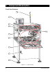
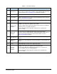
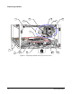
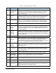
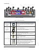
Table 3-2 Dispensing Chamber Features
Item Name Description
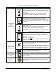
1
Fluid Pressure
Regulator
Regulates the air pressure supplied to the syringe. Systems equipped with a
Dual-Action Dispensing Head have an additional regulator for the second
dispensing valve. See the appropriate dispensing valve manual for the
recommended setting.
2
Dispensing
Head
Consists of the dispensing valve with syringe, vision system, height sensor,
and needle heater. It moves in the XYZ planes and is controlled by the
Fluidmove software and directional controls on the Control Panel.
3 Vision System
The C-718 can use the AV-700 Targeting Offset Camera (a basic vision
system), or the AV-2550 Pattern Recognition System (advanced vision
system that can be configured for edge detection or fiducial identification).
4 Syringe Contains the fluid to be dispensed and comes in a variety of sizes.
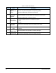
5
Dispensing
Valve
(DJ-2000
shown)
Also referred to as a pump, valve, or jet depending on the type. Dispenses
fluid onto the workpiece. It mounts on the dispensing head and holds the
syringe of dispensing fluid. Refer to the applicable dispensing valve manual
for more information.
6
Valve Air
Pressure
Regulator
Regulates the air pressure supplied to the dispensing valve. Systems with a
Dual-Action Dispensing Head have a second valve air pressure regulator for
the second fluid pump. See the appropriate dispensing valve manual for the
recommended setting.
7 Dispensing Area Area inside dispensing chamber where fluid dispensing takes place.
8 Conveyor
Moves the workpiece from upstream machines to the dispensing area and
then to downstream machines. The SMEMA compatible Conveyor is
controlled by the Fluidmove software and directional controls on the Control
Panel. C-718 Series Dispensing Systems use belt Conveyors.
9
Under Board
Support
(Optional)
Consists of a pneumatic lift table with movable supports and vacuum
support pins. Prevents the workpiece from sagging or bouncing during the
dispensing process.
10 Purge Station
Cleans the dispensing needle/nozzle and purges the dispensing valve at
user-defined intervals. A disposable plastic cup inside of the purge station
holds the purged fluid.
11 Needle Sensor Senses and transmits needle XYZ position to the Fluidmove software.
12
Under Board
Support Switch
Allows you to turn off the lift table or set it to run automatically.
13
Door Interlock
Sensors
Prevents system operation while the dispensing chamber doors are open.
14 Stop Pin Pneumatic device that physically stops the workpiece in the dispensing area.
15 Height Sensor
Measures substrate height and sends information to the system Computer.
The height information is used to position the dispensing needle/nozzle an
exact distance above the workpiece surface.