Century® C-718 Series Dispensing Systems Quick Operations Manual P/N 7207413, Revision A
NOTICE This is an Asymtek publication which is protected by copyright. Original copyright date 2005. No part of this document may be photocopied, reproduced, or translated to another language without the prior written consent of Asymtek. The information contained in this publication is subject to change without notice. Manuals on the Internet For the convenience of Asymtek customers and field service representatives, copies of this manual can be downloaded from: http://www.asymtek.com/support/manuals.
Table of Contents 1 INTRODUCTION .......................................................................................................... 1 2 SAFETY........................................................................................................................ 2 Basic Safety Precautions .........................................................................................................................2 Electrostatic (ESD) Discharge Precautions ..............................................
1 Introduction This document is intended primarily as a reference for production operators of C-718, C-718-SMT, and C-718-SMA Dispensing Systems. However, others unfamiliar with Asymtek products may also find this document useful as a general introduction to the system. Refer to the Century Series C-718/C718-SMT Installation, Operations, and Maintenance Manual for detailed information. Century C-718 Series Dispensing Systems are designed to solve the diverse needs of the fluid dispensing market.
2 Safety Basic Safety Precautions • Only trained personnel should be permitted to perform operation, maintenance, and troubleshooting procedures. • Locate, identify, and obey all safety warning labels on your system before initial use. Refer to Safety Warning Labels in this section. • Immediately push the red Emergency Machine Off (EMO) button if personnel are in danger of being injured. Refer to Emergency Shutdown in this section. • Do not wear loose clothing or jewelry while operating the system.
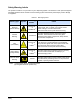
Safety Warning Labels The symbols in Table 2-1 may be found on your dispensing system or accessories to warn personnel against potentially hazardous areas. Failure to heed a warning symbol could lead to personal injury and/or damage to equipment.
Emergency Shutdown Your Century C-718 Series Dispensing System features an Emergency Machine Off (EMO) button that the operator or service technician can use to immediately stop all dispensing operations in case of emergency. This feature helps prevent injury to personnel and damage to the dispensing system and workpieces being processed. The EMO button is located on the Control Panel on the front of the dispensing system (see Figure 2-1).
Safety Interlock Switch The Safety Interlock Switch is located on the Control Panel (see Section 3 Component Description ). It is designed to restrict access to the inside of the dispensing system, based on user-defined levels of operation. The Safety Interlock has two modes: ON (l) or OFF (0). Once an Interlock safety mode is selected, the key can be removed to prevent an inadvertent mode change. The Safety Interlock is designed to work with either the Door Sensors or with the Light Curtain.
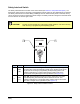
Light Beacon The Light Beacon (Figure 2-3) is a device that displays system status whenever the dispensing system is ON. The Beacon has four colored lights that can be constantly ON or flashing and has an audible alarm. The colors on the Light Beacon correspond with the System Status LED’s on the Control Panel. Table 2-2 defines the colors.
Table 2-2 Panel / Beacon Colors, Dispensing Status and Recovery Procedures Panel / Beacon Color RED YELLOW GREEN Dispensing Status Recovery Procedures ALERT All motion, outputs, valve and motion controls are disabled. One of the following conditions exists: A. Doors open or light curtain is obstructed when system is moving, INTERLOCK at I. B. System is in an abort state. A or B: 1. Close doors or remove obstruction, or change INTERLOCK to O. 2. Press DISPENSER STATUS RESET. 3. Press FIND HOME. 4.
3 Component Description Front View Features 1 2 3 4 Valve 2 Pressure Valve Pressure Fluid 2 Pressure Fluid Pressure Abort Pause 9 8 7 6 5 4 Program 3 2 1 Start 0 Z Axis Teach Conveyor Status Conveyor Interlock Recovery Dispenser V1 Status Dispenser Pause Valve Status Interlock Valve Reset V2 Find Home Reset Reset Century S E R I E S 5 15 10 A NORDSON COMPANY 10 5 6 7 8 9 Figure 3-1 C-718 Front View 8 Component Description
Table 3-1 Front View Features Item Name Description 1 Light Beacon A device that visually and audibly indicates dispensing system operating status. It has red, yellow, green, and blue status indication lights that can be solid or flashing. Refer to Light Beacon for additional information. 2 Monitor Provides the operator with FmNT displays. 3 Control Panel Buttons and switches let you control certain programming and run functions. Refer to Control Panel for details.
Dispensing Chamber 1 3 4 6 5 15 5 10 2 7 8 12 9 10 11 13 13 14 15 Figure 3-2 Dispensing Chamber Close-up (Doors Not Shown) 10 Component Description
Table 3-2 Dispensing Chamber Features Item Name Description 1 Fluid Pressure Regulator Regulates the air pressure supplied to the syringe. Systems equipped with a Dual-Action Dispensing Head have an additional regulator for the second dispensing valve. See the appropriate dispensing valve manual for the recommended setting. 2 Dispensing Head Consists of the dispensing valve with syringe, vision system, height sensor, and needle heater.
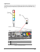
Control Panel 2 1 3 5 1 7 7 4 6 8 Figure 3-3 Control Panel Table 3-3 Control Panel Features Item No./Name Feature 1 Displays the air pressure level being supplied to the syringe. Systems equipped with a Dual-Action Dispensing Head have two gauges. Fluid Pressure Gauge 2 I = Green system ON button. 0 = Gray system OFF button. Shuts down all dispensing system components except Computer and Monitor. ON and OFF Buttons ABORT Press to abort a production run.
Table 3-3 Control Panel Features (continued) Item No./Name Feature Function Z AXIS Click and release V to move dispense head up/down 1 mm (0.001 inch). Click and hold V to move dispense head 25.4 mm/sec (1 in/sec). Click and hold (2-3 in/sec). to move dispense head 50-75 mm/sec Z-Axis Controls Press to set a desired location on the workpiece using the Fluidmove software. TEACH Two Modes: 1. Press to move the dispensing head to its XYZ home position and re-establish its “Home” reference coordinates.
Table 3-3 Control Panel Features (continued) Item No. Feature CONVEYOR STATUS PAUSE RESET INTERLOCK RECOVERY INTERLOCK 5 System Status Indicators and Interlock Switch DISPENSER STATUS RESET V1 VALVE STATUS Function Press PAUSE to stop the Conveyor. The LED lights to indicate Conveyor is stopped. Press PAUSE again to resume Conveyor movement. Press RESET to clear the Conveyor controller after a fault condition has occurred. The LED lights to indicate a fault.
Rear View Features 1 2 3 7 4 5 6 Figure 3-4 Rear View Features Component Description 15
Table 3-4 Rear View Features Item 1 2 3 4 16 Name Description Main Air Regulator and Gauge The Main Air Regulator (T-bar) controls, and the gauge indicates, the amount of air pressure supplied to the dispensing system. Conveyor Air Gauge and Regulator The Conveyor Air Regulator controls, and the gauge indicates, the air pressure supplied to the bar clamps and stop pins on the Conveyor.
4 Setup and Operation Valve Setup Figures 4-1 and 4-2 show the electrical and pneumatic connections for dispensing valves commonly used with a C-718 Series Dispensing System. For other valves, refer to the applicable valve manual.
Figure 4-2 DV-7000/DV-8000 Connections (DV-8000 shown) 18 Setup and Operation
Pneumatic Regulator Adjustment Operators may have to adjust the air pressure when the dispensing valve or application changes, or to prepare the system for maintenance or servicing. Pressure settings will depend on the application. " NOTE When decreasing pressure, lower the pressure past the target level, then rotate the adjustment knob clockwise (right) to raise pressure to the desired setting. This will help prevent false readings.
Main Air Regulator and Conveyor Air Regulator Recommended Pressure Settings: Main Air = 551.
System Start-up 3 1 Fluid 2 Pressure Fluid Pressure Abort Pause 2 Z Axis 9 8 7 6 5 4 Program 3 2 1 Start 0 Teach Conveyor Status Conveyor Pause Find Home Interlock Recovery Dispenser Status Dispenser Reset Interlock Reset AUTOTUNE INDEX HT-1200 NEEDLE HEATER SPI AL SP2 F C OMEGA CN76000 ENTER A NORDSON COMPANY 4 A NORDSON COMPANY 0 5 Figure 4-5 System Start-up Setup and Operation 21
Fluidmove Start-up 1 2 Figure 4-6 Starting Fluidmove 22 Setup and Operation
Using Fluidmove Jog Controls Jog Control Access Click on one of the following buttons or press Ctrl + J on the keyboard.
1 2 5 3 6 4 Item Description 1 Target Box (click to move dispenser to the location) 2 Y-axis Controls (moves Dispenser forward and back) 3 X-axis Controls (moves Dispenser side-to-side) 4 Dispenser Radio Button (click to activate Dispenser Jog) 5 Z-axis Controls (moves Dispensing Head up and down) 6 Home Button (moves Dispenser to “Home” position Figure 4-8 Dispenser Jog Control 24 Setup and Operation
Loading a Program " NOTE Refer to the Fluidmove User Guide or Online Help for additional information.
Pre-run Setup Routines A Prompted Setup or Scripted Setup routine should be performed: • Prior to all production runs • After a valve has been removed or reinstalled • After a new needle has been placed on the valve assembly • After moving or focusing the camera • After moving or replacing the height sensor probe assembly • Anytime you are experiencing inaccurate dispensing " NOTE Refer to the Fluidmove User Guide or Online Help for detailed information.
Scripted Setup " NOTE Refer to the Fluidmove User Guide or Online Help for additional information.
Run Production " NOTE See Table 4-1 for description of Run Window buttons. Refer to the Fluidmove User Guide or Online Help for additional information.
Table 4-1 Run Control Buttons Item Description Starts the Production Run. Go Pauses the Production Run. Pause Stops the Production Run after completing the current board. Stop Aborts the Production Run. Abort Accesses Online Help. Help Opens the Jog Window, which contains Position Controls for moving the Dispensing Head and the Conveyor. Jog Returns to the Production Window.
5 Maintenance WARNING! CAUTION! Follow appropriate safety procedures while performing system maintenance or injury to personnel and damage to the system may result. See Section 2 - Safety for details. Periodic Maintenance Table 5-1 System Maintenance Recommended Frequency Instructions 1. Clean purge boot and purge lid Daily a. Remove the purge station lid (Figure 5-1). b. Clean the boot and lid with a small bottle brush and the solvent recommended by the dispensing fluid manufacturer (see MSDS).
1 2 3 4 Item Description 1 Purge Boot (use appropriate size in Table 5-2) 2 Purge Station Lid 3 Purge Cup 4 Purge Station Figure 5-1 Purge Station Maintenance Table 5-2 Purge Boot Colors and Sizes Purge Boot Color Inside Diameter Orange 0.5 mm (0.020 in) Pink 0.8 mm (0.031 in) Green 1.1 mm (0.045 in) Olive* 3.0 mm (0.120 in) *Recommend size for nozzles.
Maintenance NAIS 2 Item 1 Conveyor Rail 2 Part Sensors 3 Conveyor Belt Pink Blue Black - Brown + - Dark On 12-24V - DC Load NQ-W20A-DC12-24V AN50530 Light On NAIS Pink Blue Black - Brown + Dark On 12-24V - DC Load NQ-W20A-DC12-24V AN50530 Light On Fr on t 1 3 Description Figure 5-2 Conveyor Maintenance 33
1 2 3 4 Item Description Item Description 1 Main Air Inlet 3 Facility Air Supply Line 2 Bowl Guard 4 Drain Button (push up to drain) Figure 5-3 Draining the Water Trap 34 Maintenance
Asymtek Headquarters 2762 Loker Avenue West Carlsbad, CA 92010-6603 USA Tel: (760) 431-1919 1-800-ASYMTEK (1-800-279-6835) P/N 7207413, Rev.