
Manual

13-6 Special Options
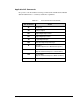
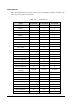
Interconnects
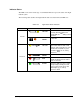
The following table of interconnects can be used for testingdevices and I/Os. Normally, only
trained service personnel use this table.
Table 13-2 Interconnects
Signal Port A Pin# Port B Pin# Port C Pin#
Input #0 1 1
Input #1 2 2
Input #2 3 3
Input #3 4 4
Input #4 5 5
Input #5 6 6
Input #6 7 7
Input #7 8 8
Abort/Stop Input 9
Pause Input 9
Collector Output #0 10 10 10
Collector Output #1 11 11 11
Collector Output #2 12 12 12
Collector Output #3 13 13 13
Collector Output #4 4 14 14
Collector Output #5 15 15 15
Collector Output #6 16 16 16
Collector Output #7 17 17 17
Isolated Ground
(for inputs)
18,30-36 18,30-36 18,30-36
Emitter Output #0 19 19 19
Emitter Output #1 20 20 20
Emitter Output #2 21 21 21
Emitter Output #3 22 22 22
Emitter Output #4 23 23 23
Emitter Output #5 24 24 24
Emitter Output #6 25 25 25
Emitter Output #7 26 26 2
No Connections 27,28,29 27,28,29 27,28,29