
Installation Manual


5-38 Power-up and Testing
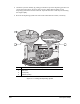
21. Calculate the variance in Heater Tooling height from end to end and front to back.
> The height variance of the Heater from left to right should be within ±0.005 inch
(±0.127 mm).
> The height variance between front and back of the Heater should be within ±0.005 inch
(±0.127 mm).
> If the tooling is determined to be out of level, call Asymtek Technical Support.
CAUTION! Only trained service technicians should attempt to adjust the level of the Lift
Tables or Heater Tooling.
22. Close the Dispenser Jog Commands dialog box to return to the Main Window.
Heater Tooling and Needle Heaters
Perform the following electrical and temperature tests, as applicable to your system configuration, to
make sure that the Heaters are functioning properly.
To electrically test Heater Tooling:
WARNING! Make sure that the Heater Tooling is cool before performing this procedure or
serious injury may occur.
1. In the FmNT Main Window, click on Tools.
2. In the Tools Window, click on
Terminal.
3. Click on
Heaters.
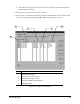
4. In the Heater Control Window, locate the loops (channels) for the Heater Tooling installed on
your system. See Figure 5-20.
5. Verify the icons in the
On/Off column indicate that each heating tool is OFF (gray). If any of
the tools are ON, double click on the yellow and red icon next to the loop name
to turn them OFF. Wait until the tools are cool (35 °C or less) as indicated by the value in the
PV (present value) column.
6. Turn off power to the dispensing system by pressing
OFF (0) on the Operator’s Console and
switch the Main Circuit Breaker
OFF (0). Lock out and tag out the power as specified in the
Safety section of this manual.
7. Open the Hatch and disconnect the electrical cable to each Heater Module.
8. Measure and record resistance between connector pins 1 and 2 for each Heater Module.
> The resistance for a Heater with one heating element should be 60 ohms.
> The resistance for a Heater with two heating elements should be 30 ohms.