
Installation Manual


Power-up and Testing 5-37
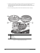
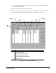
Item Description
1 Measurement Locations (approximate)
2 Heater Tooling (Contact Heater shown)
3 Front Conveyor Rail
Figure 5-19 Lift Table and Heater Tooling Level Check
16. Raise the Dispensing Head with the Z-axis slow jog button until the green LED
goes OFF.
17. Lower the Dispensing Head with the Z-axis slow jog button
just until the green LED
illuminates (one click past the LED being OFF).
18. Record the Z-axis reading displayed in the Jog Commands dialog box in the area just below
the target box. See Figure 5-11.
19. Using the Z-axis position controls, raise the Dispensing Head.
20. Repeat Steps 14 through 19 for the other three corners of the Heater Tooling. See Figure 5-19
for approximate locations.
3
1
1
2