
Installation Manual


5-26 Power-up and Testing
4. Click on the ARM/DISARM button until the “Current Arm State” reads ARMED.
> The Height Sensor Probe should be in the down position.
5. Click on OK twice to return to the Main Window.
6. In the Main Window, click on the
Jog icon .
7. In the Jog Commands dialog box, click on
Dispenser.
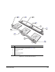
8. Using the target box or position controls, move the Height Sensor Probe over the left front
Conveyor Rail. See Figure 5-15 for the approximate location.
CAUTION! Avoid contacting Board Sensors or other components attached to the rail.
9. Using the position controls, lower the Dispensing Head toward the rail until the green LED
on the Height Sensor goes ON.
10. Raise the Dispensing Head with the Z-axis slow jog button
until the green LED
goes OFF.
11. Lower the Dispensing Head with the Z-axis slow jog button
just until the green LED
illuminates (one click past the LED being OFF).
12. Record the Z-axis reading displayed in the Jog Commands dialog box in the area just below
the target box. See Figure 5-11.
13. Raise the Dispensing Head and, using only Y-axis position controls, move the Height Sensor
Probe over the left end of the rear rail.
? NOTE A slight X-axis movement may be needed to avoid obstacles.
14. Repeat Steps 8 through 13 at the center and far right end of the rails. See Figure 5-15 for
approximate locations.
15. Calculate the variance in rail height from end to end and between front and back rails.
> The height variance of each rail from one end to the other should be within ±0.005 inch
(±0.127 mm).
> The height variance between front and back rails at the measured locations should be
within ±0.005 inch (±0.127 mm).
> If the rail is determined to be out of level, call Asymtek Technical Support.
CAUTION! Only trained service technicians should attempt to adjust the level of the
Conveyor Rails.