
Installation Manual


Power-up and Testing 5-11
Impingement Air Flowmeters
Perform the following procedure to check function of the Impingement Air Valve and Flowmeters.
To check function of Impingement Air Valve and Flowmeters:
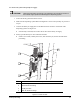
1. Locate the Impingement Air Valve and Flowmeters in the Front Cabinet of the dispensing
system. See Figure 5-5.
2. Open the Impingement Air Valve by turning the handle counterclockwise such that it is
parallel with the airline. Listen for leaks.
> If there is an air leak, identify the source, shut off the air valve, and fix the leak before
proceeding.
3. While monitoring the readouts on the three Flowmeters, turn the Flowmeter Adjustment
Knobs counterclockwise until maximum airflow is achieved.
> The flow indicators should show an increase in airflow.
4. While monitoring the readouts on the three Flowmeters, turn the Flowmeter Adjustment
Knobs clockwise to lessen the flow.
> The flow indicators should show a decrease in airflow.
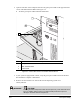
5. Restore maximum airflow and open the dispensing system Hatch. Verify air is coming out of
the holes in Impingement Heater at each Conveyor station.
> If air is not flowing out of the Heater, check the pneumatic connections.
EMO Check on Main Interface PWA
Perform the following procedure to check function of EMO buttons while viewing LEDs on the
Computer Main Interface PWA. .
?NOTE This procedure assumes that the dispensing system has already been powered up and the
Hatch is closed.
TIP This procedure is performed more efficiently if there is a technician at the front of the
dispensing system and an assistant at the rear of the dispensing system.
To check EMO function:
1. Open the Front Cabinet Door and locate the Computer.
WARNING! CAUTION!
Touching the electrical components inside the Computer may cause electrical
shock injury. In addition, make sure that you observe ESD precautions to prevent
damage to sensitive electrical components.