
Installation Manual


5-10 Power-up and Testing
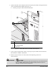
4. After the Valve 1 Digital Gauge has been initialized, shut off air pressure by turning the
Valve 1 Fluid Air Pressure Regulator Knob counterclockwise. Make sure the Gauge settles
at 0 psi.
5. Increase air pressure to 30 to 40 psi (206 to 275 kPa) by turning the Valve 1 Fluid Air
Pressure Regulator Knob clockwise.
6. Monitor the Valve 1 Fluid Pressure Gauge display to make sure that the pressure builds at a
steady rate. Listen for any air leaks as the pressure builds.
> If there is an air leak, identify the source, shut off the facility air, and fix the leak before
proceeding.
> If the Gauge does not seem to be working properly, contact Asymtek Technical Support.
7. Repeat Steps 1 through 6 for the Valve 2 Fluid Pressure Gauge if applicable to your
system configuration.
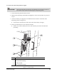
Item Description
1 Valve 1 Fluid Air Digital Gauge
2 Valve Air Regulator and Gauge
3 Valve 1 Fluid Air Adjustment Knob
4 Valve 2 Fluid Air Adjustment Knob
5 Tooling Air Shutoff Valve
6 Tooling Air Regulator and Gauge
7 Impingement Air Flowmeters
8 Valve 2 Fluid Air Digital Gauge
Figure 5-5 Gauge and Regulator Locations
6
5
8
3
1
7
4
2