
Installation Manual


4-4 Component Installation
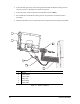
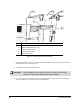
Item Description
1 Alignment Pin (1 of 2)
2 Hole for Alignment Pin (1 of 2)
3 X-Y Servo Motor Cover
4 Captive Thumbscrews
5 Servo Shelf Cover
Figure 4-2 Removing the Servo Shelf Cover
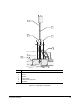
8. Position the rubber grommet on the Beacon Mast such that it seats properly with the cutout in
the Right Side Cover. See Figure 4-3.
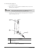
9. Carefully reinstall the Servo Shelf Cover.
CAUTION! When reinstalling the Servo Shelf Cover, avoid contacting the Servo-supply
Capacitors or the XY Servo Interface Board may be damaged.
10. Use your fingers or a flat head screwdriver to tighten the two quick-release screws holding
the Servo Shelf Cover in place. Do not use thread locker.
3
451
2