
Installation Manual


Component Installation 4-1
4 Component Installation
Overview
This section describes the installation and setup procedures for the following components:
• Dispensing Valves (Valves, Pumps, and Jets)
• Monitor
• Light Beacon
CAUTION! If the dispensing system is being installed in a clean room, remove all packaging
material and follow facility-recommended procedures before moving components
into the clean room.
Installing Dispensing Valves
If they have not already been installed at the Asymtek factory, install the Valve(s), Pump(s), or Jet(s) on
your dispensing system in accordance with the applicable Dispensing Valve Installation and
Operations Manual.
Installing the Monitor
CAUTION! This procedure should only be performed by a trained service technician.
Tools and Materials Needed
• 3-mm Hex Key • Removable Thread Locker (P/N 40-0019)
• Computer Monitor (P/N 194712)
To install the Monitor:
? NOTE Apply removable thread locker to all threaded fasteners unless otherwise noted.
1. Locate the Monitor in the Accessories Crate and remove from its box.
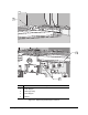
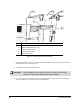
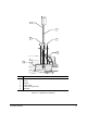
2. Remove the two 3-mm mounting screws in the back of the Monitor
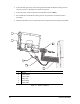
3. Align the Monitor with the Monitor Mount Block and install the two 3-mm mounting screws.
Torque to 25 in-lbs (0.288 kg-m). See Figure 4-1.
4. Locate the light gray Video Cable coming from underneath the Monitor Swing Arm and
connect it to the Monitor as shown in Figure 4-1. Tighten the connector thumbscrews
hand tight. Do not use thread locker.