
Installation Manual


X-1000 Installation Checklist
6 of 13
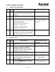
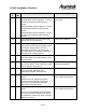
F. Valve Operation
Step
#
Done
(9)
Test Performed Main Function(s) Tested
29. Ensure that no Valves are plugged into the
system. Verify that the Valve control LEDS
(A0-A3) on the side of the Z-head are all lit.
Valve ID circuitry and 555
control
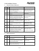
30. From the FMNT->TOOLS->IO TEST->
Select V1_Valve
Verify that the pressure switches from the
black to the blue line on the Valve 1 ports.
Using a receiver head, verify that the proper
regulator is controlling the pressure on this
port.
Bit operation and pneumatics
routing
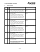
31. From the FMNT->TOOLS->IO TEST->
Select V1_Fluid
This should toggle the Valve1 fluid pressure
line Using a receiver head, verify that the
proper regulator is controlling the pressure
on this port.
Bit operation and pneumatics
routing
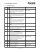
32. From the FMNT->TOOLS->IO TEST->
Select V2_Valve
Verify that the pressure switches from the
black to the blue line on the Valve 2 ports.
Using a receiver head, verify that the proper
regulator is controlling the pressure on this
port.
Bit operation and pneumatics
routing
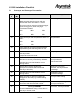
33. From the FMNT->TOOLS->IO TEST->
Select V2_Fluid
This should toggle the Valve 2 fluid pressure
line. Using a receiver head, verify that the
proper regulator is controlling the pressure
on this port.
Bit operation and pneumatics
routing
34. From the FMNT->TOOLS->IO TEST->
Select Dual_action
This should toggle the dual action pressure
line. Using a receiver head, verify that the bit
is toggling the appropriate port.
Dual action plumbing